Nov 26, 2013
Technology增加一个VLAN设备:
$ ip link add link eth0 name eth0.100 type vlan id 100
查看增加的VLAN设备详情:
$ ip -d link show eth0.100
增加一个IPV4地址:
	$ ip addr add 192.168.100.1/24 brd 192.168.100.255 dev eth0.100
	$ ip link set dev eth0.100 up
关闭一个VLAN设备:
$ ip link set dev eth0.100 down
移除一个VLAN设备:
$ ip link delete eth0.100
Nov 25, 2013
Technology###Preparation
####STM Standard Peripheral Lib
Download Link for STSW-STM32054STM32F10x standard peripheral library :
http://www.st.com/web/catalog/tools/FM147/CL1794/SC961/SS1743/PF257890
Unsip the downloaded library and you will get several folders, the Libraries folder is the pure libs.
####Cross-Compiler for STM32
Download the cross-compiler from CodeSourcery ARM EABI toolchain - Mentor Graphics:
https://sourcery.mentor.com/sgpp/lite/arm/portal/subscription?@template=lite
You have to choose EABI version. Download and install it, you will get “arm-none-eabi-” prefixed cross-compiler.
####Eclipse plugins
Help-> Install New Software, Add the URL for gnuarm:
http://gnuarmeclipse.sourceforge.net/updates
Then Install CDT GNU Cross Development Tools , after install the plugin, you will asked to reboot, just reboot. Now your preparation is OK.
###Create a new project
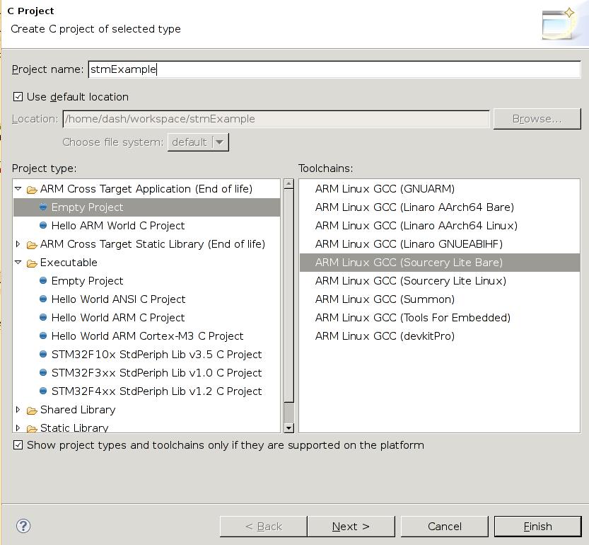
In Eclipse, Click File->New->C project, choose “ARM Cross Target Applcation (End of life)", choose “Empty Project” “ARM Linux GCC(Sourcery Lite Bare), give the Project name and click Next Button, then click Finish. you will see the newly created project in the Project Explorer.
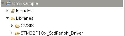
Copy the Library files into your own project, take “stmExample” project for example:
	[Trusty@DashArch STM32F10x_StdPeriph_Lib_V3.5.0]$ pwd
	/media/y/embedded/stm32/dev/lib/STM32F10x_StdPeriph_Lib_V3.5.0
	[Trusty@DashArch STM32F10x_StdPeriph_Lib_V3.5.0]$ cp -r  Libraries/ ~/workspace/stmExample/
Your project should seem like this:
Now you have to prepare your startup file, notice you have to use “S” suffixed file name, and you have to remove the remaining directory except the .S file:
	[Trusty@DashArch startup]$ pwd
	/home/Trusty/workspace/stmExample/Libraries/CMSIS/CM3/DeviceSupport/ST/STM32F10x/startup
	[Trusty@DashArch startup]$ ls
	arm  gcc_ride7  iar  TrueSTUDIO
	[Trusty@DashArch startup]$ cp TrueSTUDIO/startup_stm32f10x_hd.s ./startup_stm32f10x_hd.S
	[Trusty@DashArch startup]$ ls
	arm  gcc_ride7  iar  startup_stm32f10x_hd.S  TrueSTUDIO
	[Trusty@DashArch startup]$ rm -rf TrueSTUDIO/ iar/ gcc_ride7/ arm/
	[Trusty@DashArch startup]$ ls
	startup_stm32f10x_hd.S
Create a directory named src to contains your own project files.
	[Trusty@DashArch stmExample]$ mkdir src
	[Trusty@DashArch stmExample]$ pwd
	/home/Trusty/workspace/stmExample
	[Trusty@DashArch stmExample]$ ls
	Libraries  src
Copy the project files into “src” directory:
	[Trusty@DashArch STM32F10x_StdPeriph_Template]$ ls
	EWARM  HiTOP  main.c  MDK-ARM  Release_Notes.html  RIDE  stm32f10x_conf.h  stm32f10x_it.c  stm32f10x_it.h  system_stm32f10x.c  TrueSTUDIO
	[Trusty@DashArch STM32F10x_StdPeriph_Template]$ cp stm32f10x_* ~/workspace/stmExample/src/
	[Trusty@DashArch STM32F10x_StdPeriph_Template]$ pwd
	/media/y/embedded/stm32/dev/lib/STM32F10x_StdPeriph_Lib_V3.5.0/Project/STM32F10x_StdPeriph_Template
Copy the link script to root directory of your project:
	[Trusty@DashArch STM32100B-EVAL]$ pwd
	/media/y/embedded/stm32/dev/lib/STM32F10x_StdPeriph_Lib_V3.5.0/Project/STM32F10x_StdPeriph_Template/TrueSTUDIO/STM32100B-EVAL
	[Trusty@DashArch STM32100B-EVAL]$ cp stm32_flash.ld  ~/workspace/stmExample/
You have to modify the link script according to your own flash layout and memory layout, My CPU is STM32F103VC, which has 48K RAM and 256K Flash, so the configuration is listed as:
/*
Linker subscript for STM32F051 definitions with 64K Flash and 8K RAM
Copyright RAISONANCE 2007
!!! This file is automatically generated by RIDE !!!
Do not modify it, as it will be erased at every link.
You can use, copy and distribute this file freely, but without any warranty.
*/

/* Memory Spaces Definitions */

ENTRY(Reset_Handler)

MEMORY
{
  FLASH (rx) : ORIGIN = 0x08000000, LENGTH = 256K
  RAM  (xrw) : ORIGIN = 0x20000000, LENGTH = 48K
}

/* highest address of the user mode stack */
_estack = 0x2000c000;


/*
Common part of the linker scripts for STR71x devices in FLASH mode
(that is, the FLASH is seen at 0)
Copyright RAISONANCE 2005
You can use, modify and distribute this file freely, but without any warranty.
*/

/* Sections Definitions */

SECTIONS
{
    /* for Cortex devices, the beginning of the startup code is stored in the .isr_vector section, which goes to FLASH */
    .isr_vector :
    {
	. = ALIGN(4);
        KEEP(*(.isr_vector))            /* Startup code */
	. = ALIGN(4);
    } >FLASH

    /* the program code is stored in the .text section, which goes to Flash */
    .text :
    {
	    . = ALIGN(4);

        *(.text)                   /* normal code */
        *(.text.*)                 /* -ffunction-sections code */
        *(.rodata)                 /* read-only data (constants) */
        *(.rodata*)                /* -fdata-sections read only data */
        *(.glue_7)                 /* TBD - needed ? */
        *(.glue_7t)                /* TBD - needed ? */

	/* Necessary KEEP sections (see http://sourceware.org/ml/newlib/2005/msg00255.html) */
	KEEP (*(.init))
	KEEP (*(.fini))

	    . = ALIGN(4);
        _etext = .;
	    /* This is used by the startup in order to initialize the .data section */
        _sidata = _etext;
    } >FLASH

    /* This is the initialized data section
    The program executes knowing that the data is in the RAM
    but the loader puts the initial values in the FLASH (inidata).
    It is one task of the startup to copy the initial values from FLASH to RAM. */
    .data  : AT ( _sidata )
    {
	    . = ALIGN(4);
        /* This is used by the startup in order to initialize the .data secion */
        _sdata = . ;
        _data = . ;

        *(.data)
        *(.data.*)
        *(.RAMtext)

	    . = ALIGN(4);
	    /* This is used by the startup in order to initialize the .data secion */
   	    _edata = . ;
    } >RAM

    /* This is the uninitialized data section */
    .bss :
    {
	    . = ALIGN(4);
        /* This is used by the startup in order to initialize the .bss secion */
        _sbss = .;
        _bss = .;

        *(.bss)
        *(.bss.*) /* patched by elias - allows the use of -fdata-sections */
        *(COMMON)

	    . = ALIGN(4);
	    /* This is used by the startup in order to initialize the .bss secion */
   	 _ebss = . ;
    } >RAM

    PROVIDE ( end = _ebss );
    PROVIDE ( _end = _ebss );

    __exidx_start = .;
    __exidx_end = .;

    /* after that it's only debugging information. */

    /* remove the debugging information from the standard libraries */
    /DISCARD/ :
    {
     libc.a ( * )
     libm.a ( * )
     libgcc.a ( * )
     }

    /* Stabs debugging sections.  */
    .stab          0 : { *(.stab) }
    .stabstr       0 : { *(.stabstr) }
    .stab.excl     0 : { *(.stab.excl) }
    .stab.exclstr  0 : { *(.stab.exclstr) }
    .stab.index    0 : { *(.stab.index) }
    .stab.indexstr 0 : { *(.stab.indexstr) }
    .comment       0 : { *(.comment) }
    /* DWARF debug sections.
       Symbols in the DWARF debugging sections are relative to the beginning
       of the section so we begin them at 0.  */
    /* DWARF 1 */
    .debug          0 : { *(.debug) }
    .line           0 : { *(.line) }
    /* GNU DWARF 1 extensions */
    .debug_srcinfo  0 : { *(.debug_srcinfo) }
    .debug_sfnames  0 : { *(.debug_sfnames) }
    /* DWARF 1.1 and DWARF 2 */
    .debug_aranges  0 : { *(.debug_aranges) }
    .debug_pubnames 0 : { *(.debug_pubnames) }
    /* DWARF 2 */
    .debug_info     0 : { *(.debug_info .gnu.linkonce.wi.*) }
    .debug_abbrev   0 : { *(.debug_abbrev) }
    .debug_line     0 : { *(.debug_line) }
    .debug_frame    0 : { *(.debug_frame) }
    .debug_str      0 : { *(.debug_str) }
    .debug_loc      0 : { *(.debug_loc) }
    .debug_macinfo  0 : { *(.debug_macinfo) }
    /* SGI/MIPS DWARF 2 extensions */
    .debug_weaknames 0 : { *(.debug_weaknames) }
    .debug_funcnames 0 : { *(.debug_funcnames) }
    .debug_typenames 0 : { *(.debug_typenames) }
    .debug_varnames  0 : { *(.debug_varnames) }
}
Now create a sample main.c under the src directory and input your source code.
###Configure the project
Right click your project, select Properties, C/C++ Build -> Settings, ARM Linux GCC Assembler(Sourcery Lite Bare)/Preprocessor, add a Defined symbols(-D), also you have to add this into ARM Linux GCC Compiler(Sourcery Lite Bare):
	STM32F10X_HD
	USE_STDPERIPH_DRIVER
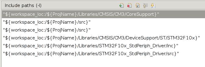
In ARM Linux GCC C Compiler(Sourcery Lite Bare)-> Directories, add Include paths(-i) add following:
Specify the link script:
ARM Linux GCC CLinker(Sourcery Lite Bare) -> General, Script file(-T)
/home/Trusty/workspace/stm32archlinux/stm32_flash.ld
###Build and Debug
Right click the project and click “Build project”, then you got your project compiling and linking, finally you got your Binary named stmExample.elf.
Now we can use OpenOCD for writing the image into the flash and debugging it.
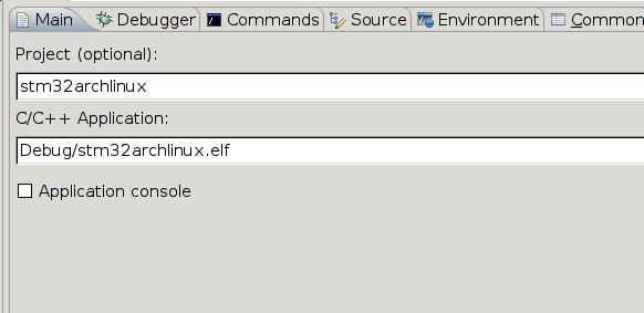
Run->Debug Configuration, you will see Zylin Embedded debug(Native) is available, right click and choose “Create new”, create a new debug item.
Choose the Main:
Choose the Debugger:
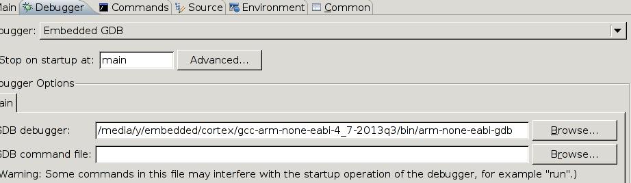
Choose Commands:
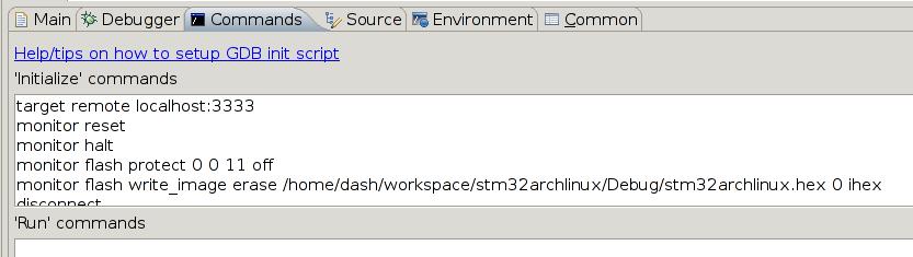
The configuration file is :
	target remote localhost:3333
	monitor reset
	monitor halt
	monitor flash protect 0 0 11 off
	monitor flash write_image erase /home/Trusty/workspace/stm32archlinux/Debug/stm32archlinux.hex 0 ihex
	disconnect
	target remote localhost:3333
	monitor reset
	monitor halt
Open your own openocd, and then using eclipse to connect the gdb. Remember “toggle breakpoint” and you will get a hardware breakpoint. Enjoy the debugging.
Nov 25, 2013
Technology###Hardware
Joggler
Intel(R) Atom(TM) CPU Z520 @ 1.33GHz Dual Core
MemTotal: 504480 kB
Harddisk: 500G External USB.
###System and Software
Download the Ubuntu Base/Server 12.04 LTS (Precise) (Joggler Image v1.4 - 09/04/2013) from the
http://joggler.exotica.org.uk/ubuntu/
From the ubuntu website we know 12.04 LTS will supported to 2017, I think that fits my needs.
Unzip the download image:
	gunzip ubuntu_base_12.04-v1.4-ext4.img.gz
	dd if=./ubuntu_base_12.04-v1.4-ext4.img of=/dev/sdc bs=1M
The use this external usb disk for booting up the joggler. After joggler has been booted up, install coresponding packages.
###Prevent Hard disk from hiberating
Add following lines to crontab -e
*/4 * * * * fdisk -l /dev/uba>/dev/null && echo abc>/root/done.txt
Nov 22, 2013
TechnologyAdd existing user to specified group
The problem is : why I can’t use hddtemp? This is because hddtemp need priviledge for accessing the disk related equipment.
	[Trusty@XXXyyy ~]$ whoami
	Trusty
	[Trusty@XXXyyy ~]$ groups
	root log kvm users vboxusers
	[Trusty@XXXyyy ~]$ su root
	Password:
	[root@XXXyyy Trusty]# groups
	root bin daemon sys adm disk wheel log
But this didn’t solve the problem, I have to add prividge in /etc/sudoes,
	# visudo
	Trusty ALL = NOPASSWD: /usr/bin/hddtemp
Therefore in the configuration file of conky I need to replace the hddtemp with “sudo hddtemp”, everything will be displayed.
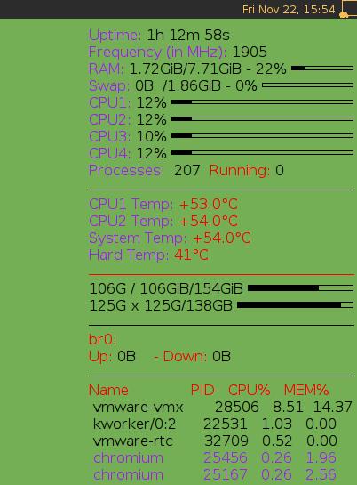
Now testing the Conky
After you have installed conky, the first thing for you to do is to edit its configuration file, to decide what to display on your own widget, my configuration file is listed as following:
alignment top_right
background yes
border_width 1
cpu_avg_samples 2
default_color black
default_outline_color blue
default_shade_color blue
draw_borders no
draw_graph_borders yes
draw_outline no
draw_shades no
use_xft yes
xftfont AR PL KaitiM GB:size=12
gap_x 5
gap_y 30
minimum_size 280 5
net_avg_samples 2
no_buffers yes
out_to_console no
out_to_stderr no
extra_newline no
own_window yes
own_window_class Conky
own_window_type override
##设置conky的默认背景色
##own_window_colour 573049
##很重要,只有启用argb才能透明,但是如果窗口属性如果设置为override,可能无法生效
#own_window_argb_visual yes
##设置透明的alpha值0-255,0为透明,255不透明
#own_window_argb_value 0
##own_window_argb_visual true
##own_window_argb_value 120
own_window_transparent yes
double_buffer yes
stippled_borders 0
update_interval 1
uppercase no
use_spacer none
show_graph_scale no
show_graph_range no

TEXT
#${color red}${font AR PL KaitiM GB:style=Blod:size=17}    ${time %Y.%m.%d %H:%M:%S}
#${font AR PL KaitiM GB:style=Blod:size=12}
#${font AR PL KaitiM GB:style=Blod:size=12}${scroll 16 $nodename - $sysname $kernel on $machine}
#$hr
#${font AR PL KaitiM GB:style=Blod:size=14}${color green}${exec cal}
#$hr
${font AR PL KaitiM GB:style=Blod:size=12}${color purple}Uptime:$color $uptime
${color purple}Frequency (in MHz):$color $freq
#${color purple}Frequency (in GHz):$color $freq_g
${color purple}RAM: $color$mem/$memmax - $memperc% ${membar 4}
${color purple}Swap: $color$swap/$swapmax - $swapperc% ${swapbar 4}
${color purple}CPU1: $color${cpu cpu1}% ${cpubar 4}
${color purple}CPU2: $color${cpu cpu2}% ${cpubar 4}
${color purple}CPU3: $color${cpu cpu3}% ${cpubar 4}
${color purple}CPU4: $color${cpu cpu4}% ${cpubar 4}
${color purple}Processes: $color $processes  ${color red}Running:$color $running_processes
$hr
#${color red}Temp:
${color purple}CPU1 Temp: ${color red}${exec sensors | grep 'Core 0' | awk {'print $3'}}
${color purple}CPU2 Temp: ${color red}${exec sensors | grep 'Core 1' | awk {'print $3'}}
${color purple}System Temp: ${color red}${exec sensors | grep 'temp1' | tail -1 | awk {'print $2'}}
${color purple}Hard Temp: ${color red}${exec sudo hddtemp /dev/sda -n -u=C}°C
$hr
#${color red}File systems:
${color black}${exec df -h | grep /dev/sda3 | awk {'print $3'}} / $color${fs_used /}/${fs_size /} ${fs_bar 6 /}
${exec df -h | grep /dev/sda2 | awk {'print $3'}} x $color${exec df -h | grep /dev/sda2 | awk {'print $3'}}/138GB ${fs_bar 6 /media/ubuntu}
#${exec df -h | grep /dev/sda8 | cut -c40-43} /boot $color${fs_used /boot}/${fs_size /boot} ${fs_bar 6 /boot}
$hr
#${color red}Networking:
#${color red}eth0:
#Up:$color ${upspeed eth0} ${color red} - Down:$color ${downspeed eth0}
${color red}br0:
Up:$color ${upspeed br0} ${color red} - Down:$color ${downspeed eth0}
#${color red}ppp0:
#${color red}Up:$color ${upspeed ppp0} ${color red} - Down:$color ${downspeed ppp0}
$hr
${color red}Name              PID   CPU%   MEM%
${color black} ${top name 1} ${top pid 1} ${top cpu 1} ${top mem 1}
${color black} ${top name 2} ${top pid 2} ${top cpu 2} ${top mem 2}
${color black} ${top name 3} ${top pid 3} ${top cpu 3} ${top mem 3}
${color purple} ${top name 4} ${top pid 4} ${top cpu 4} ${top mem 4}
${color purple} ${top name 5} ${top pid 5} ${top cpu 5} ${top mem 5}
In fact I didn’t finished the Translucent, so I use the Transparent, a little bit ugly, but it’s OK.
Add it into awesome
Simply add one line in your ~/.config/awesome/rc.lua could solve the problem:
awful.util.spawn("conky")
Now you can enjoy your Conky.
Nov 22, 2013
Technology###OpenOCD Device Scan
Install and view the OpenOCD:
	$ pacman -S openocd
	[Trusty@XXXyyy debian_octopress]$ openocd -v
	Open On-Chip Debugger 0.7.0 (2013-11-02-01:53)
	Licensed under GNU GPL v2
	For bug reports, read
		http://openocd.sourceforge.net/doc/doxygen/bugs.html
Insert your openJTAG debug board, and view its connection:
	[Trusty@XXXyyy debian_octopress]$ lsusb
	Bus 001 Device 016: ID 1457:5118 First International Computer, Inc. OpenMoko Neo1973 Debug board (V2+)
From the dmesg information:
	[15767.673553] usb 1-1: new full-speed USB device number 11 using xhci_hcd
	[15767.695990] usb 1-1: Device not responding to set address.
	[15767.938262] usb 1-1: Device not responding to set address.
	[15768.140725] usb 1-1: device not accepting address 11, error -71
	[15768.421057] usb 1-1: new full-speed USB device number 13 using xhci_hcd
	[15769.015800] usbcore: registered new interface driver usbserial
	[15769.016012] usbcore: registered new interface driver usbserial_generic
	[15769.016075] usbserial: USB Serial support registered for generic
	[15769.020028] usbcore: registered new interface driver ftdi_sio
	[15769.020050] usbserial: USB Serial support registered for FTDI USB Serial Device
	[15769.020458] usb 1-1: Ignoring serial port reserved for JTAG
	[15769.020499] ftdi_sio 1-1:1.1: FTDI USB Serial Device converter detected
	[15769.020544] usb 1-1: Detected FT2232C
	[15769.020548] usb 1-1: Number of endpoints 2
	[15769.020550] usb 1-1: Endpoint 1 MaxPacketSize 64
	[15769.020553] usb 1-1: Endpoint 2 MaxPacketSize 64
	[15769.020555] usb 1-1: Setting MaxPacketSize 64
	[15769.026647] usb 1-1: FTDI USB Serial Device converter now attached to ttyUSB0
	[15975.012193] usb 1-1: USB disconnect, device number 13
	[15975.012449] ftdi_sio ttyUSB0: FTDI USB Serial Device converter now disconnected from ttyUSB0
	[15975.012465] ftdi_sio 1-1:1.1: device disconnected
	[15975.270658] usb 1-1: new full-speed USB device number 14 using xhci_hcd
	[15975.355869] usb 1-1: Ignoring serial port reserved for JTAG
	[15975.366867] ftdi_sio 1-1:1.1: FTDI USB Serial Device converter detected
	[15975.366902] usb 1-1: Detected FT2232C
	[15975.366904] usb 1-1: Number of endpoints 2
	[15975.366906] usb 1-1: Endpoint 1 MaxPacketSize 64
	[15975.366908] usb 1-1: Endpoint 2 MaxPacketSize 64
	[15975.366909] usb 1-1: Setting MaxPacketSize 64
	[15975.371933] usb 1-1: FTDI USB Serial Device converter now attached to ttyUSB0
	[16608.914153] usb 1-1: USB disconnect, device number 14
	[16608.914371] ftdi_sio ttyUSB0: FTDI USB Serial Device converter now disconnected from ttyUSB0
	[16608.914402] ftdi_sio 1-1:1.1: device disconnected
	[16609.394763] usb 1-1: new full-speed USB device number 15 using xhci_hcd
	[16609.395097] usb 1-1: Device not responding to set address.
	[16609.598734] usb 1-1: Device not responding to set address.
	[16609.801899] usb 1-1: device not accepting address 15, error -71
	[16609.962045] usb 1-1: new full-speed USB device number 16 using xhci_hcd
	[16609.962371] usb 1-1: Device not responding to set address.
	[16610.250376] usb 1-1: Ignoring serial port reserved for JTAG
	[16610.261380] ftdi_sio 1-1:1.1: FTDI USB Serial Device converter detected
	[16610.261428] usb 1-1: Detected FT2232C
	[16610.261431] usb 1-1: Number of endpoints 2
	[16610.261433] usb 1-1: Endpoint 1 MaxPacketSize 64
	[16610.261435] usb 1-1: Endpoint 2 MaxPacketSize 64
	[16610.261437] usb 1-1: Setting MaxPacketSize 64
	[16610.266397] usb 1-1: FTDI USB Serial Device converter now attached to ttyUSB0
From the above information we could know, Now we have a new Serial port named ttyUSB0, and also a FT2232C debug port. Currently we don’t use Serial Port, FT2232 is all we want to configure.
###OpenOCD Configuration
We have to make a cfg file for OpenOCD to use. There are some pre-defined configuration files for us to refer under the directory of “/usr/share/openocd/scripts/", since we know the debug board information and we know exactly the development board info, we can easily write our own OpenOCD startup scripts.
Get the interface definition via:
	[Trusty@XXXyyy interface]$ pwd
	/usr/share/openocd/scripts/interface
	[Trusty@XXXyyy interface]$ grep "1457" ./ -r
	./neodb.cfg:ft2232_vid_pid 0x1457 0x5118
	./ftdi/neodb.cfg:ftdi_vid_pid 0x1457 0x5118
So we directly copy the neodb.cfg to our openocd.cfg under our home directory. But the usb name of our OpenOCD is changed,
ft2232_device_desc "USB<=>JTAG&RS232
The definition is taken from the output of “lsusb -v -d 1457:5118”
We also want to define the port for telnet and gdb connection
	#########daemon configuration####
	telnet_port 4444
	gdb_port 3333
The Target configuration is taken from the /usr/share/openocd/scripts/target/stm32f1x.cfg, which is the definition of the stm32f1x. Copy them directly to your own config file.
Finally your configuration file should be listed as:
#########daemon configuration####
telnet_port 4444
gdb_port 3333

########Interface Info###########
################################################
# Since our board takes the same vid_pid
# We directly use openmoko's definition.
################################################
#
# Openmoko USB JTAG/RS232 adapter
#
# http://wiki.openmoko.org/wiki/Debug_Board_v3
#
interface ft2232
ft2232_device_desc "USB<=>JTAG&RS232"
ft2232_layout jtagkey
ft2232_vid_pid 0x1457 0x5118

########Board Info###########
# Adjust Work-area size (RAM size) according to MCU in use:
#STM32F103VC --> 48KB
#STM32F103RB --> 20KB
#set WORKAREASIZE 0x5000
# STM32F103RE --> 64KB
# set WORKAREASIZE 0x10000

# reset_config parameter (see OpenOCD manual):
# none --> srst and trst of MCU not connected to JTAG device
# srst_only --> only srst of MCU connected to JTAG device
# trst_only --> only trst of MCU connected to JTAG device
# srst_and_trst --> srst and trst of MCU connected to JTAG device
# default setting: "reset_config none" will produce a single reset via SYSRESETREQ (JTAG commands) at reset pin of MCU
#reset_config none


#script for stm32f1x family

if { [info exists CHIPNAME] } {
   set _CHIPNAME $CHIPNAME
} else {
   set _CHIPNAME stm32f1x
}

if { [info exists ENDIAN] } {
   set _ENDIAN $ENDIAN
} else {
   set _ENDIAN little
}

# Work-area is a space in RAM used for flash programming
# By default use 16kB
if { [info exists WORKAREASIZE] } {
   set _WORKAREASIZE $WORKAREASIZE
} else {
   set _WORKAREASIZE 0x4000
}

# JTAG speed should be <= F_CPU/6. F_CPU after reset is 8MHz, so use F_JTAG = 1MHz
adapter_khz 1000

adapter_nsrst_delay 100
jtag_ntrst_delay 100

#jtag scan chain
if { [info exists CPUTAPID] } {
   set _CPUTAPID $CPUTAPID
} else {
  # See STM Document RM0008
  # Section 26.6.3
   set _CPUTAPID 0x3ba00477
}
jtag newtap $_CHIPNAME cpu -irlen 4 -ircapture 0x1 -irmask 0xf -expected-id $_CPUTAPID

if { [info exists BSTAPID] } {
   # FIXME this never gets used to override defaults...
   set _BSTAPID $BSTAPID
} else {
  # See STM Document RM0008
  # Section 29.6.2
  # Low density devices, Rev A
  set _BSTAPID1 0x06412041
  # Medium density devices, Rev A
  set _BSTAPID2 0x06410041
  # Medium density devices, Rev B and Rev Z
  set _BSTAPID3 0x16410041
  set _BSTAPID4 0x06420041
  # High density devices, Rev A
  set _BSTAPID5 0x06414041
  # Connectivity line devices, Rev A and Rev Z
  set _BSTAPID6 0x06418041
  # XL line devices, Rev A
  set _BSTAPID7 0x06430041
  # VL line devices, Rev A and Z In medium-density and high-density value line devices
  set _BSTAPID8 0x06420041
  # VL line devices, Rev A
  set _BSTAPID9 0x06428041

}
jtag newtap $_CHIPNAME bs -irlen 5 -expected-id $_BSTAPID1 \
	-expected-id $_BSTAPID2 -expected-id $_BSTAPID3 \
	-expected-id $_BSTAPID4 -expected-id $_BSTAPID5 \
	-expected-id $_BSTAPID6 -expected-id $_BSTAPID7 \
	-expected-id $_BSTAPID8 -expected-id $_BSTAPID9

set _TARGETNAME $_CHIPNAME.cpu
target create $_TARGETNAME cortex_m -endian $_ENDIAN -chain-position $_TARGETNAME

$_TARGETNAME configure -work-area-phys 0x20000000 -work-area-size $_WORKAREASIZE -work-area-backup 0

# flash size will be probed
set _FLASHNAME $_CHIPNAME.flash
flash bank $_FLASHNAME stm32f1x 0x08000000 0 0 0 $_TARGETNAME

# if srst is not fitted use SYSRESETREQ to
# perform a soft reset
cortex_m reset_config sysresetreq
[root@XXXyyy target]# openocd -f /media/y/embedded/stm32/dev/openocd.cfg -f ./stm32f1x.cfg