Nov 29, 2013
Technology使用定时器的好处是,等待某个时隙的同时还可以干别的事,而定时器的时间一到,得到一个中断后对应执行中断函数中的服务例程而已。STM32的定时器非常之复杂而强大,配置和使用都要花很大精力。
打开TIM2线的程序如下:
void TIM_Configuration(void)
{
	//......

	/* TIM2 clock enable */
  	RCC_APB1PeriphClockCmd(RCC_APB1Periph_TIM2, ENABLE);

	//......
有关定时器的设置如下:
	/* 基础设置*/
	TIM_TimeBaseStructure.TIM_Period = 8000;			//计数值
	TIM_TimeBaseStructure.TIM_Prescaler = 7200-1;    	//预分频,此值+1为分频的除数
	TIM_TimeBaseStructure.TIM_ClockDivision = 0x0;  	//
	TIM_TimeBaseStructure.TIM_CounterMode = TIM_CounterMode_Up; 	//向上计数
这里设置的是定时器溢出控制,分频值的计算就是上述代码中提到的预分频的设置。 TIM2属于低速总线,这条总线最高只能达到36M的速度,芯片内部还有一个X2的倍频器,用于将低速的32M倍频成72M, 库中已经默认有实现。所以我们这里使用的TIM2其速度依然是72M, 如果预设分频为7200的话,分频后的结果就是72M/7200=10K(72000000/7200). 我们可以把这个值变大或变小,以获得更慢或更快的分频速度。
计数值设置的是8000,计数器向上计数到8000的时候会溢出。因而溢出的时间是8000/10K=0.8s 比较值的设置如下:
	u16 CCR1_Val = 4000;
	u16 CCR2_Val = 2000;
	u16 CCR3_Val = 1000;
	u16 CCR4_Val = 500;
	/* 比较通道1*/
	TIM_OCInitStructure.TIM_OCMode = TIM_OCMode_Inactive;      		//输出比较非主动模式
	TIM_OCInitStructure.TIM_Pulse = CCR1_Val;
	TIM_OCInitStructure.TIM_OCPolarity = TIM_OCPolarity_High;		//极性为正

	TIM_OC1Init(TIM2, &TIM_OCInitStructure);
	TIM_OC1PreloadConfig(TIM2, TIM_OCPreload_Disable);				//禁止OC1重装载,其实可以省掉这句,因为默认是4路都不重装的.
则得到的四个比较值的大小分别为: 4000/10000=0.4s, 2000/10000=0.2s, 1000/10000=0.1s, 500/10000=0.05
不同的分频值设置,如果把Prescaler设置为14400-1,则得到的分频结果是72000000/14400=5K,对应的时间也随着调整。
简单来说,我们需要得到分频结果,还有就是预设的几个值与其结果作运算得出的真正时间。
Timer到达后会产生中断,通道的捕获中断发生时,对应会执行相应的动作。这些中断处理函数是在"stm32f10x_it.c"中实现的:
/*******************************************************************************
* Function Name  : TIM2_IRQHandler TIM2中断
* Description    : This function handles TIM2 global interrupt request.
* Input          : None
* Output         : None
* Return         : None
*******************************************************************************/

void TIM2_IRQHandler(void)
{
	if (TIM_GetITStatus(TIM2, TIM_IT_CC1) != RESET)
	{
		/*必须清空标志位*/
		TIM_ClearITPendingBit(TIM2, TIM_IT_CC1);

		/*点亮LED5*/
		LED5_ON;
		//LED1直接操作寄存器方式的闪烁
		GPIOA->ODR^=GPIO_Pin_8;

	}
	else if (TIM_GetITStatus(TIM2, TIM_IT_CC2) != RESET)
	{
		TIM_ClearITPendingBit(TIM2, TIM_IT_CC2);

		/*点亮LED6*/
		LED6_ON;
	}
	else if (TIM_GetITStatus(TIM2, TIM_IT_CC3) != RESET)
	{
		TIM_ClearITPendingBit(TIM2, TIM_IT_CC3);

		/* 点亮LED7*/
		LED7_ON;
	}
	else if (TIM_GetITStatus(TIM2, TIM_IT_CC4) != RESET)
	{
	  	TIM_ClearITPendingBit(TIM2, TIM_IT_CC4);

	  	/*点亮LED8*/
		LED8_ON;

	}
	else if (TIM_GetITStatus(TIM2, TIM_IT_Update) != RESET)
	{
		TIM_ClearITPendingBit(TIM2, TIM_IT_Update);
		/*熄灭所有LED*/
		LED5_OFF;
		LED6_OFF;
		LED7_OFF;
		LED8_OFF;
	}
}
需要注意的是, GPIOA->ODR^=GPIO_Pin_8, 直接操作了寄存器,用于将LED1反向输出。GPIO->ODR就是GPIOA的输出寄存器,而LED1用的就是GPIOA的8脚, 在这个中断函数中,如果TIM_IT_CC1的值达到了,将点亮LED5和控制LED1的闪烁。
在IO速度要求很高的场合,建议采用IO直接操作寄存器的方法,比用库函数要快得多。
Nov 28, 2013
Technology###有关电路
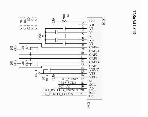
上一章讲的是12864的基础知识。这一章里来看12864和stm32板的连接和驱动的问题。
有关12864小LCD的连接,在PDF中我们可以找到如下的表项:
| 功能模块 | 占用模块 | 备注 |
|---|
| 12864小LCD | PC4,PB2,PB11,PB13,PB15 | PC4:A0,同时也是 CH375 和 TFT 的 A0;PB2:BOOT1,LCD 的 CS 脚;PB11:28J60 和大小 LCD 的复位脚 |
再结合电路图:
关于GPIO口的设置,我们可以看到有这样的定义:
	typedef enum
	{ GPIO_Mode_AIN = 0x0,
	  GPIO_Mode_IN_FLOATING = 0x04,
	  GPIO_Mode_IPD = 0x28,
	  GPIO_Mode_IPU = 0x48,
	  GPIO_Mode_Out_OD = 0x14,
	  GPIO_Mode_Out_PP = 0x10,
	  GPIO_Mode_AF_OD = 0x1C,
	  GPIO_Mode_AF_PP = 0x18
	}GPIOMode_TypeDef;
而在stm32的Datasheet中有如下的配置模式:
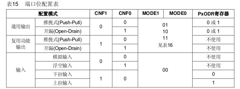
最低的8个bit和表中是一一对应的,其中通用输出/复用功能输出的mode1/mode0的值为00.
因为PB15是MOSI2口, PB13是SCK2口,所以这两个管脚需要被设置为AF模式的。AF代表复用功能。PP代表push-pull.
	/* PB15-MOSI2,PB13-SCK2*/
	/* Why PB14 should be enabled? */
	GPIO_InitStructure.GPIO_Pin = GPIO_Pin_13 |GPIO_Pin_14 | GPIO_Pin_15;
	GPIO_InitStructure.GPIO_Speed = GPIO_Speed_50MHz;
	GPIO_InitStructure.GPIO_Mode = GPIO_Mode_AF_PP;
	GPIO_Init(GPIOB, &GPIO_InitStructure);
PB11和PB2属于output口,所以直接设置为out口即可。
有关SPI2口的配置, 在STM中的代码如下:
	/* SPI2 configuration */
	    SPI_Cmd(SPI2, DISABLE); 												//必须先禁能,才能改变MODE
	SPI_InitStructure.SPI_Direction = SPI_Direction_2Lines_FullDuplex;		//两线全双工
	SPI_InitStructure.SPI_Mode = SPI_Mode_Master;							//主
	SPI_InitStructure.SPI_DataSize = SPI_DataSize_8b;						//8位
	SPI_InitStructure.SPI_CPOL = SPI_CPOL_High;								//CPOL=1 时钟悬空高
	SPI_InitStructure.SPI_CPHA = SPI_CPHA_2Edge;							//CPHA=1 数据捕获第2个
	SPI_InitStructure.SPI_NSS = SPI_NSS_Soft;								//软件NSS
	SPI_InitStructure.SPI_BaudRatePrescaler = SPI_BaudRatePrescaler_2;		//2分频
	SPI_InitStructure.SPI_FirstBit = SPI_FirstBit_MSB;						//高位在前
	SPI_InitStructure.SPI_CRCPolynomial = 7;								//CRC7

	    SPI_Init(SPI2, &SPI_InitStructure);
	SPI_Cmd(SPI2, ENABLE);
###有关SPI总线
SPI接口是Motorola 首先提出的全双工三线同步串行外围接口,采用主从模式(Master Slave)架构;支持多slave模式应用,一般仅支持单Master。时钟由Master控制,在时钟移位脉冲下,数据按位传输,高位在前,低位在后(MSB first);SPI接口有2根单向数据线,为全双工通信,目前应用中的数据速率可达几Mbps的水平。
stm32中关于SPI传送字节的函数编写
	static u8 SPIByte(u8 byte)
	{
		/*等待发送寄存器空*/
		while((SPI2->SR & SPI_I2S_FLAG_TXE)==RESET);
	    /*发送一个字节*/
		SPI2->DR = byte;
		/* 等待接收寄存器有效*/
		while((SPI2->SR & SPI_I2S_FLAG_RXNE)==RESET);
		return(SPI2->DR);
	}
命令和数据是调用这个函数写入的,我们需要注意的是时序,在写入总线时需要先拉低/高A0线
	//写命令
	void LcdCmd(u8 cmd)
	{
		CSLCDS_L;
		A0_L;
		//__nop();
		;
		SPIByte(cmd);
		//__nop();
		;
		CSLCDS_H;
	}

	//写数据
	void LcdDat(u8 dat)
	{
		CSLCDS_L;
		A0_H;
		//__nop();
		;
		SPIByte(dat);
		//__nop();
		;
		CSLCDS_H;
	}
Nov 28, 2013
Technology###如何控制液晶屏幕
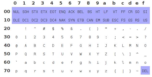
ASCII码的可打印字符的范围在0x20 ~ 0x7f之间, 0x20 是空格字符,0x7f是delete字符。 最开始我们需要在内存中建立一张关于可打印字符的表。用于表示在液晶屏幕上如何显示出该字符,即该字符的点阵排列。
下图是可以打印的ASCII/Unicode 0-127的值:
点阵数组:
	const u8 Asii8[] = {
		0x00,0x00,0x00,0x00,0x00,0x00,0x00,0x00,
		0x06,0x5F,0x06,0x00,0x00,0x07,0x03,0x00,
		0x07,0x03,0x00,0x24,0x7E,0x24,0x7E,0x24,
		0x00,0x24,0x2B,0x6A,0x12,0x00,0x00,0x63,
		0x13,0x08,0x64,0x63,0x00,0x36,0x49,0x56,
来个例子:
	#: 0x00, 0x24, 0x7e, 0x24, 0x7e, 0x24
	00000000
	00100100
	01111110
	00100100
	01111110
	00100100
对应的1代表将该点的液晶点点上。
要注意,实际的显示应该是倒过来的,即: 把你的脖子顺时针转90度看上面的二进制表达式。
在LCD上设置需要写入的坐标,
	/**************************************************************
	**函数名 :LcdSetXP
	**功能:设置坐标**
	**注意事项:这里设置的坐标不是X,Y,而是X,PAGE.因为黑白屏一次写入的数据为8个点,而且为竖
	**			式写入,故纵坐标是以页为单位,64个点共8页
	***************************************************************/
	void LcdSetXP(u8 x,u8 page)
	{
		LcdCmd((page&0x07)+0xb0);	//设置页指针
	    LcdCmd((x>>4)|0x10);
	    LcdCmd(x&0x0f);
	}
128X64的屏幕一共有8192个点, 每一个字符用48个点来表示,即8X6。所以每一个字的X坐标长度应该是6, 而Y坐标应该是8. 一个page代表8个点。
考虑下面代码:
	LcdSetXP(0,1);
	LcdChar8('T');
	LcdChar8('E');
	LcdChar8('S');
	LcdChar8('T');
	LcdChar8(' ');
	LcdChar8('O');
	LcdChar8('K');
	LcdChar8('!');

	LcdSetXP(0,2);
	LcdChar8('T');
	LcdSetXP(6,2);
	LcdChar8('E');
	LcdSetXP(24,2);
	LcdChar8('S');
	LcdChar8('T');
	LcdChar8(' ');
	LcdChar8('O');
	LcdChar8('K');
	LcdChar8('!');
得到的结果应该是:
TEST OK!
TE ST OK!
对应上面的解释不难明白在屏幕上填写字符的原理。
有关在屏幕上写字符的函数是:
/**************************************************************
**函数名 :LcdChar8
**功能:写一个宽6高8的ASCII
**注意事项:这里忽略了坐标的设置,此函数作为子函数被其他函数调用,使用前需要设置坐标
			使用内部的点阵表
***************************************************************/
void LcdChar8(char chr)
{
	u8 i;
	u8* p_data;

	/* 0x20 is the space character
	 * 0x7f is the delete character
	 * Seems all of the printable character are listed in the global array
	 */
	if((chr<0x20)||(chr>0x7f))
	{
		return;
	}

	/* Asii8 is the global variable(Glbal Array), So now we retrieve the
	 * character's address via first address plus the (asii code number)*6
	 * Because, each entry size if 6, all of the entry start from 0x20
	 */
	p_data = (u8*)Asii8 + (chr-0x20)*6;	//要写字符的首地址

	for(i=0;i<6;i++)
	{
		LcdDat(*p_data++);
	}
}
举例说明, !的字符表示为
00000000
00000000
00000110
01011111
00000110
00000000
则看起来应该像:
000100
001110
000100
000000
000100
000000
把1想象为点,就能对应想象出!在屏幕上的样子。
原有的代码中关于GPIO初始化的时候,多初始化了一个PB14口,删除后一切正常。
Nov 27, 2013
TechnologyFor those code files which contains gb2312 or gbk format, we can use following scripts for automatically convert them to UTF-8 conpatiable format files.
#!/bin/sh
export LANG="zh_CN.utf8"
export LC_ALL="zh_CN.utf8"
#for file in `find . -name "*.h"`
for file in `find . -name "*.c"`
do
	echo $file
	enca -L zh_CN -x UTF-8 $file
done
Nov 27, 2013
Technology板子是09年入手的,但是一直没时间好好玩,最近端起来觉得有必要好好研究一番。为了以后翻阅方便,全中文记下来。
###12864
通常所说的12864LCD显示块是所说的点阵液晶显示模块,就是由128X64个液晶显示点组成的一个128列X64行的阵列,所以也就叫成了12864。每个显示点都对应着有一位二进制数,0表示灭,1表示亮。存储这些点阵信息的RAM被称为显示数据存储器。如果要显示某个图形或汉字就是将相应的点阵信息写入到对应的存储单元中。图形或汉字的点阵信息是由自己设计,这时候问题的关键是显示点在液晶屏上的位置与其在存储器中的地址之间的关系。
显示点在64X64液晶屏上的位置由列号(line,0~63)与行号(line,0~63)确定。512X8 bits RAM中某个存储单元的地址由页地址(Xpage,0~7)和列地址(Yaddress,0~63)确定。每个存储单元存储8个液晶点的显示信息。也就是说,一个页的大小是8. 运算关系则是64x64=(64x8)x8=512x8.
由于多数液晶显示模块的驱动电路是由一片行驱动器和两片列驱动器构成,所以12864液晶屏实际上是由左右两块独立的64X64液晶屏拼接而成,每半屏有一个512X8 bits显示数据RAM。左右半屏驱动电路及存储器分别由片选信号CS1和CS2选择。(少数厂商为了简化用户设计,在模块中增加译码电路,使得128X64液晶屏就是一个整屏,只需一个片选信号。)
如如果点亮12864的屏中(20,30)位置上的液晶点,因列地址30小于64,该点在左半屏第29列,所以CS1有效;行地址20除以8取整得2,取余得4,该点在RAM中页地址为2,在字节中的序号为4;所以将二进制数据00010000(也可能是00001000,高低顺序取决于制造商)写入Xpage=2,Yaddress=29的存储单元中即点亮(20,30)上的液晶点。
这是为了为了使液晶点位置信息与存储地址的对应关系更直观关,将64X64液晶屏从上至下8等分为8个显示块,每块包括8行X64列个点阵。每列中的8行点阵信息构成一个8bits二进制数,存储在一个存储单元中。(需要注意:二进制的高低有效位顺序与行号对应关系因不同商家而不同)存放一个显示块的RAM区称为存储页。即64X64液晶屏的点阵信息存储在8个存储页中,每页64个字节,每个字节存储一列(8行)点阵信息。因此存储单元地址包括列地址(Yaddress,0~63)和页地址(Xpage,0~7)。
以上就是对于12864点阵液晶显示器的原理介绍。
在DX32开发板上的液晶是怎么一回事呢?它的封装图如下:
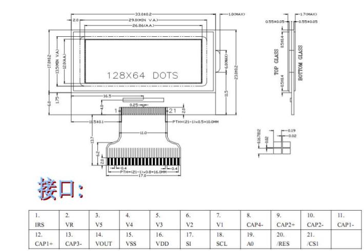
Datasheet有72页,乱七八糟的会讲一大堆。但是事实上我们只需要关注和软件有关的方面,拿一个很简单的开启/关闭LCD的例子来说,DataSheet里有这样的表格:
| Command | A0 /RD /WR | D7 D6 D5 D4 D3 D2 D1 D0 | Function |
|---|
| Display On/OFF | 0 1 0 | 1 0 1 0 1 1 1 1 | LCD Display ON |
| Display On/OFF | 0 1 0 | 1 0 1 0 1 1 1 0 | LCD Display OFF |
那么会有对应的代码:
	/**************************************************************
	**函数名:LcdOnOff
	**功能:开关LCD
	***************************************************************/
	void LcdOnOff(u8 onoff)
	{
	     if(onoff>0)
			 LcdCmd(0xaf);       //开显示
	     else
			 LcdCmd(0xae);          	//关显示
	}
0xaf的二进制的值是1010 1111, 而0xae的值则是1010 1110, 这点在手册中容易引起混淆,因为它操蛋的把前面的一系列值都省略了,表格里的才是完整的应该发送的命令。
再拿一个例子来说,
	/**************************************************************
	**函数名:LcdInit
	**功能:初始化LCD,初始化后需要用LcdCmd(0xaf)命令打开显示
	***************************************************************/
	const u8 LCD_Tab[] = {		/*0x26改0x27可增加对比度*/
		0xa2,0xa0,0xc8,0xf8,0x00,0x26,0x2f,0x81,0x05,0xa4,0xa6,0xac,0x00,0xee,0x40
	};
	void LcdInit(void)
	{
		u16 i;
		RSTLCDS_L;
		for(i=0;i<65530;i++);
		RSTLCDS_H;

		/* Why we have to write 15 times for the LCD_Tab? */
		for(i=0;i<15;i++)
			LcdCmd(LCD_Tab[i]);
		LcdCmd(0xaf);       //开显示
	}
在初始化LCD的时候我们需要依次写入命令,这里我们把命令做成一个数组,就是LCD_Tab数组, 那么命令的格式如下:
0xa2 LCD bits set, 0 means normal displaying
0xa0 ADC Select. Set the display RAM address SEG output corresponding, 0 means normal.
0xc8 Common Output Set, means reverse direction.
0xf8 Booster ratio.
所有这些在DataSheet中均有详细说明。
总之,对于12864,我们只要把它看成是一个“黑盒子”,输入对应的值,盒子上就能显示出怎样的值,如此就可以得到我们要的结果。
