Dec 7, 2013
Technology###ALSA普通用户无声
只有root才能听到声音,其他一概是哑巴,解决方案:
	$ sudo apt-get install acl
	$ sudo setfacl -m u:Your_Username:rw /dev/snd/*
等于说赋予了普通用户(Your_Username)访问/dev/snd下所有设备的读写权限。这时候打开mplayer就可以听到MP3播放声了。
###使用tsocks和ssh转发穿越防火墙
ssh -qTfnN -D 1394 xxx@xxx.xxx.xxx.xxx
这样可以在本地打开一个socks代理,127.0.0.1:1394
安装tsocks
$ sudo apt-get install tsocks
配置tsocks
	# vim /etc/tsocks.conf
	# Local networks
	# For this example this machine can directly access 192.168.0.0/255.255.255.0
	# (192.168.0.*) and 10.0.0.0/255.0.0.0 (10.*)

	local = 192.168.0.0/255.255.255.0
	local = 10.0.0.0/255.0.0.0
	server = 127.0.0.1
	server_port = 1394
	server_type = 5
试听音乐:
tsocks mplayer http://www.live365.com/play/wkhr
但是,用vlc总是提示失败。
###安装archlinux for raspberryPI
下载并解压得到img文件,而后:
	[Trusty@XXXyyy arch_rasp]$ fdisk -l archlinux-hf-2013-07-22.img

	Disk archlinux-hf-2013-07-22.img: 1.8 GiB, 1960837120 bytes, 3829760 sectors
	Units: sectors of 1 * 512 = 512 bytes
	Sector size (logical/physical): 512 bytes / 512 bytes
	I/O size (minimum/optimal): 512 bytes / 512 bytes
	Disklabel type: dos
	Disk identifier: 0x00057540

	Device                       Boot     Start       End  Blocks  Id System
	archlinux-hf-2013-07-22.img1           2048    186367   92160   c W95 FAT32 (LBA)
	archlinux-hf-2013-07-22.img2         186368   3667967 1740800   5 Extended
	archlinux-hf-2013-07-22.img5         188416   3667967 1739776  83 Linux
拷贝出根分区:
	$ mount ./archlinux-hf-2013-07-22.img -o offset=96468992 /mnt
	$ tar cjvf mnt.tar.bz2 /mnt
然后将mnt.tar.bz2解压到某硬盘分区,则可以用该硬盘启动raspberryPI
	$ pacman -Syu --noconfirm
	$ pacman -S tigervnc
	$ pacman -S alsa-utils lxde mplayer vlc vim
   	$ pacman -S xf86-video-fbdev
   	$ pacman -S alsa-utils alsa-firmware alsa-lib alsa-plugins
	$ pacman -S sudo
然后我们可以编辑出一个vncserver
	$ vncserver
	$ vim /root/.vnc/xstartup
	[ -r $HOME/.Xresources ] && xrdb $HOME/.Xresources
	xsetroot -solid grey
	xterm -geometry 80x24+10+10 -ls -title "$VNCDESKTOP Desktop" &
	#twm &
	startlxde &
	$ vncserver -kill :1
	$ vncserver
添加普通用户的权限和vnc:
	$ visudo
	root ALL=(ALL) ALL
	Trusty ALL=(ALL) ALL
	Trusty ALL=(ALL) NOPASSWD: ALL
###Start playing on boot
每次允许自动登录:
	[Trusty@XXXyyy ~]$ sudo mkdir /etc/systemd/system/getty@tty1.service.d
	[Trusty@XXXyyy ~]$ cat /etc/systemd/system/getty\@tty1.service.d/autologin.conf
	[Service]
	ExecStart=
	ExecStart=-/usr/bin/agetty --autologin Trusty --noclear %I 38400 linux
安装screen
$ pacman -S screen
增加自定义服务:
	[root@alarmpi ~]# cat /etc/systemd/system/radio.service
	[Unit]
	Description=My Radio
	After=network.target

	[Service]
	RemainAfterExit=yes
	ExecStart=/usr/bin/autoradio &

	[Install]
	WantedBy=multi-user.target
编写autoradio脚本:
	[root@alarmpi ~]# cat /usr/bin/autoradio
	#!/bin/bash
	screen -d -m sudo -u Trusty cvlc --aout oss http://www.live365.com/play/wkhr --http-proxy=http://10.0.0.221:9001
如果想添加管理
	[root@alarmpi ~]# cat /usr/bin/autoradio
	#!/bin/bash
	screen -d -m sudo -u Trusty cvlc --aout oss http://www.live365.com/play/wkhr --http-proxy=http://10.0.0.221:9001 --http-port=5202 --http-password=xxxxxx
好了,这个Internet Radio就写好了。Enjoy it!!!
Dec 6, 2013
Technology###Package Installation
Install virt-viewer for browsing the virtual machine desktop. For default spicec is not OK.
	$ pacman -S gtk-vnc
	$ yaourt -S spice-gtk3
	$ yaourt -S virt-viewer
Install virt-manager
	[root@DashArch Trusty]# pacman -S virt-manager
	[root@DashArch Trusty]# systemctl start libvirtd.service
	[root@DashArch Trusty]# systemctl enable  libvirtd.service
	ln -s '/usr/lib/systemd/system/libvirtd.service' '/etc/systemd/system/multi-user.target.wants/libvirtd.service'
	[root@DashArch Trusty]# ps -ef | grep libvirt
	root      8852     1  5 15:23 ?        00:00:00 /usr/bin/libvirtd -p /var/run/libvirtd.pid
###启动支持spice Server的qemu
-vga qxl -spice port=5988,disable-ticketing将使能spice
./run-qemu -boot d -m 1024 -enable-kvm -drive file=./fpgawindows.qcow2,if=ide -drive file=./fake.qcow2,if=virtio -cdrom ./virtio-win-0.1-74.iso -usb -vga qxl -spice port=5988,disable-ticketing -localtime
在本地或者远程访问spice server:
$ spice -h 127.0.0.1 -p 5988
但是ArchLinux上的X Server会出现问题,具体解决方案未明了。然而在Ubuntu上则是可以顺利访问的。
###启动支持VNC的Qemu
	./run-qemu -boot d  -m 1024 -enable-kvm -drive file=./fpgawindows.qcow2,if=ide -drive file=./fake.qcow2,if=virtio -cdrom ./virtio-win-0.1-74.iso -usb -vga std -nographic  -localtime -vnc :33
启动后vncviewer :33则可连接到qemu的窗口
###启动Qemu,以std方式
全新启动:
./run-qemu -boot d -m 1024 -enable-kvm -drive file=./fpgawindows.qcow2,if=ide -drive file=./fake.qcow2,if=virtio -cdrom ./virtio-win-0.1-74.iso -usb -vga std -localtime `
保存状态: ctl+alt+2
$ savevm booted
启动到上一次保存的状态:
$ ./run-qemu -boot d -m 1024 -enable-kvm -drive file=./fpgawindows.qcow2,if=ide -drive file=./fake.qcow2,if=virtio -cdrom ./virtio-win-0.1-74.iso -usb -vga std -localtime --loadvm booted
Dec 6, 2013
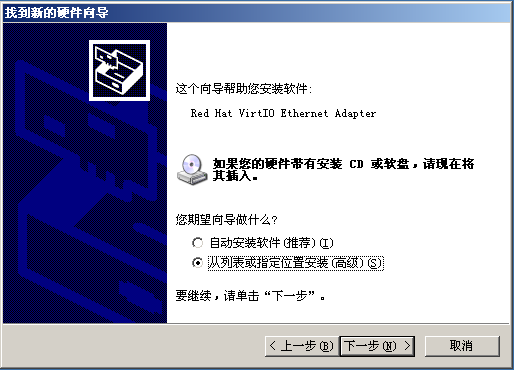
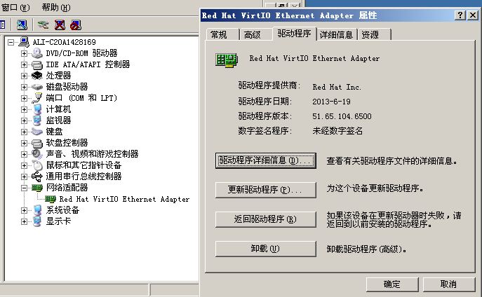
TechnologyDownload the iso file from the redhat repository:
http://alt.fedoraproject.org/pub/alt/virtio-win/latest/images/images/images/bin/src/
Start the qemu with the following command :
./run-qemu -hda fpgawindows.qcow2 -m 1024 -cdrom ./virtio-win-0.1-74.iso -drive file=./fake.qcow2,if=ide
In run-qemu, the actual command is:
qemu-system-i386 -net nic,model=virtio,macaddr=$macaddr -net tap,ifname="$IFACE" $*
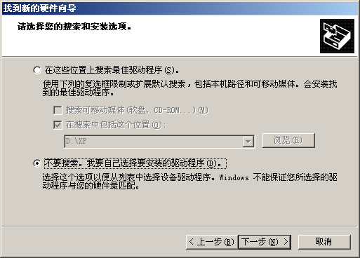
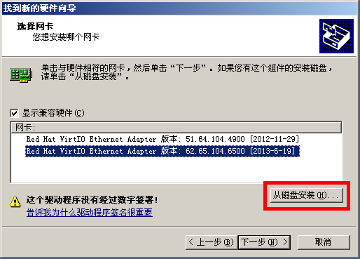
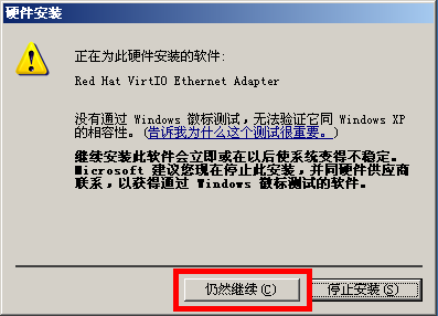
Then, follow the following images to operate:
Dec 5, 2013
TechnologyStrangely, I cannot enable the multiple SSH connections on OpenWRT.
The configuration file is listed as:
	config autossh
		option ssh	'-N -T -R 4381:localhost:22 root@XXX.xxx.xxx.xxx '
		option gatetime	'0'
		option monitorport	'20000'
		option poll	'600'
	#config autossh
	#	option ssh	'-L -N -T 10.0.0.1:9009:1XX.XX.XX.XXX:8000 xxx@xxx.xxx.xxx.xxx '
	#	option gatetime	'0'
	#	option monitorport	'20001'
	#	option poll	'600'
But only 1 connection could be enabled.
I doubt this is because of the startup scripts for /etc/init.d/autossh. I should change its methods.
	start() {
		config_load 'autossh'
		config_foreach start_instance 'autossh'
	}
But how to read and display the configuration files? It seems the multiple selections is hard to config…..
Dec 2, 2013
Technology###Installation
Update repository and install samba and samba services.
	$ sudo apt-get update
	$ sudo apt-get install samba smbfs
###Configuration
Add a new samba user:
	Trusty@joggler:~$ sudo smbpasswd -a Trusty
	[sudo] password for Trusty:
	New SMB password:
	Retype new SMB password:
Editing the /etc/samba/smb.conf:
	[samba]
	   comment = samba for ethernet users
	   path = /media/samba
	   valid users = Trusty
	   public = no
	   writable = yes
	   printable = no
	   create mask = 0765

	[homes]
	   comment = Home Directories
	   browseable = no

	security = user
	username map = /etc/samba/smbusers
Adding the mapping of the system user to samba user:
	Trusty@joggler:/media$ cat /etc/samba/smbusers
	Trusty="Trusty"
Restarting the samba service and now you can login with your new username and password.
###Configure easy
swat for samba, its description is listed as:
swat - Samba Web Administration Tool
$ sudo apt-get install swat xinetd
edit the configuration files:
	Trusty@joggler:/etc/samba$ cat /etc/xinetd.d/swat
	# description: SWAT is the Samba Web Admin Tool. Use swat \
	#              to configure your Samba server. To use SWAT, \
	#              connect to port 901 with your favorite web browser.
	service swat
	{
	        port    = 901
	        socket_type     = stream
	        wait    = no
	        user    = root
	        server  = /usr/sbin/swat
	        log_on_failure  += USERID
	        disable = no
	}
After restart xinetd, we can access http://YourIP:901 for configuration.
###Mount the samba partition
We can add this line to the ~/.bashrc, then use mountsamba we could mount the samba disk to our own mounting point.
alias mountsamba='sudo mount -t cifs //10.0.0.11/samba1/ -o user=Trusty,password=Trustywill,workgroup=WORKGROUP /media/samba'
On Windows it’s very convinient to mount the shared samba, but on Linux, only root could write to the samba disk , why?
###NFS
Installation:
	$ sudo apt-get install nfs-kernel-server
	$ sudo apt-get install rpcbind
Configuration of the nfs server:
	Trusty@joggler:~$ cat /etc/exports
	/home/Trusty 10.0.0.221(rw,sync,no_subtree_check) 10.0.0.11(rw,sync,no_subtree_check)
Restart the service of nfs:
	$ sudo service nfs-kernel-server restart
In client machine, Just add following lines to your /etc/fstab
	10.0.0.11:/home/Trusty   /media/nfs   nfs4   rsize=8192,wsize=8192,timeo=14,intr,_netdev	0 0
Restart and now in your own /media/nfs you will see the destination nfs directory.