Dec 11, 2013
Technology###Serial Preparation
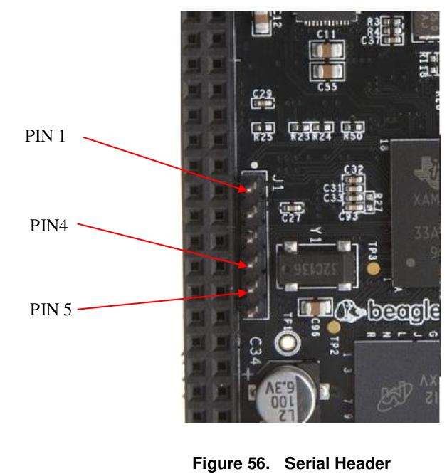
The serial port image is as following:


###Failure information
The bootup failure information is listed as following:
	Running uenvcmd ...
	reading zImage
	3345240 bytes read in 383 ms (8.3 MiB/s)
	reading /dtbs/am335x-boneblack.dtb
	24884 bytes read in 10 ms (2.4 MiB/s)

	Starting kernel ...

	Uncompressing Linux... done, booting the kernel.

	Error: unrecognized/unsupported machine ID (r1 = 0x00000e05).

	Available machine support:

	ID (hex)        NAME
	ffffffff        Generic OMAP4 (Flattened Device Tree)
	ffffffff        Generic AM33XX (Flattened Device Tree)
	ffffffff        Generic OMAP3-GP (Flattened Device Tree)
	ffffffff        Generic OMAP3 (Flattened Device Tree)
	0000060a        OMAP3 Beagle Board
	00000a9d        IGEP OMAP3 module
	00000928        IGEP v2 board
	00000ae7        OMAP4 Panda board

	Please check your kernel config and/or bootloader.
This is because the configuration file of the uEnv.txt is not right, the right one should be listed as following:
	kernel_file=zImage
	initrd_file=uInitrd
	serverip=10.0.0.11
	ipaddr=10.0.0.122
	rootpath=/media/debianroot
	console=ttyO0,115200n8

	loadzimage=load mmc ${mmcdev}:${mmcpart} ${loadaddr} ${kernel_file}
	loadinitrd=load mmc ${mmcdev}:${mmcpart} 0x81000000 ${initrd_file}; setenv initrd_size ${filesize}
	loadfdt=load mmc ${mmcdev}:${mmcpart} ${fdtaddr} /dtbs/${fdtfile}

	netargs=setenv bootargs console=${console} ${optargs} root=/dev/nfs nfsroot=${serverip}:${rootpath},vers=3 rw ip=${ipaddr}
	#mmcargs=setenv bootargs console=${console} root=${mmcroot} rootfstype=${mmcrootfstype} ${optargs}

	#mmc uenvcmd
	#uenvcmd=run loadzimage; run loadfdt; run mmcargs; bootz ${loadaddr} - ${fdtaddr}

	#just zImage
	boot_ftd=run loadzimage; run loadfdt
	uenvcmd=run boot_ftd; run netargs; bootz ${loadaddr} - ${fdtaddr}
And remember to modify some files:
	root@arm:~# cat /etc/network/interfaces
	# interfaces(5) file used by ifup(8) and ifdown(8)
	auto lo
	iface lo inet loopback

	auto eth0
	iface eth0 inet static
	address 10.0.0.122
	netmask 255.255.255.0
	gateway 10.0.0.1
Add following lines in /etc/inittab:
T0:23:respawn:/sbin/getty -L ttyO0 115200 vt102
Next time when you boot up the beaglebone, it will use the NFS files.
Tips: when your ownership of su is not right, you will meet"set uid failed” The solution is by Changing the ownership of the su used file;
chmod 4755 /bin/su
###NFS Server items
/etc/exports file items:
/media/debianroot 10.0.0.1/24(rw,sync,no_subtree_check,no_root_squash) 10.0.0.11(rw,sync,no_subtree_check,no_root_squash)
Restart the nfs server:
	/etc/init.d/nfs-kernel-server
	#or
	service nfs-kernel-server restart
tar files into your directory:
tar xvfp /media/nfs/beaglebone/debian-7.1-bare-armhf-2013-08-25/armhf-rootfs-debian-wheezy.tar -C /media/debianroot/
Dec 10, 2013
Technology###Building Preparation
Create a new directory for stroing all of the items related to beaglebone.
	cd /media/nfs/
	mkdir beaglebone
	cd beaglebone/
Download the cross-compiler from linaro toolchain binary website. And add it to the environment variables.
	wget -c https://launchpad.net/linaro-toolchain-binaries/trunk/2013.10/+download/gcc-linaro-arm-linux-gnueabihf-4.8-2013.10_linux.tar.xz
	tar xJf gcc-linaro-arm-linux-gnueabihf-4.8-2013.10_linux.tar.xz
	export CC=`pwd`/gcc-linaro-arm-linux-gnueabihf-4.8-2013.10_linux/bin/arm-linux-gnueabihf-
	# Test the cross-compiler
	${CC}gcc --version
Checkout the U-boot:
	git clone git://git.denx.de/u-boot.git
	cd u-boot/
	git checkout v2013.10 -b tmp
Patching U-boot:
	wget https://raw.github.com/eewiki/u-boot-patches/master/v2013.10/0001-am335x_evm-uEnv.txt-bootz-n-fixes.patch
	patch -p1 < 0001-am335x_evm-uEnv.txt-bootz-n-fixes.patch
Configure and compile the U-boot:
	make ARCH=arm CROSS_COMPILE=${CC} distclean
	make ARCH=arm CROSS_COMPILE=${CC} am335x_evm_config
	make ARCH=arm CROSS_COMPILE=${CC}
Checkout the kernel:
	git clone git://github.com/RobertCNelson/linux-dev.git
	cd linux-dev
	git checkout origin/am33x-v3.12 -b tmp
Now we got our kernel and U-boot available. The next step is to build a filesystem:
wget -c https://rcn-ee.net/deb/minfs/raring/ubuntu-13.04-minimal-armhf-2013-08-25.tar.xz
Prepare the mmc card.
	export DISK=/dev/mmcblk0
	[Trusty@XXXyyy beaglebone]$ sudo dd if=/dev/zero of=${DISK} bs=1M count=16
	16+0 records in
	16+0 records out
	16777216 bytes (17 MB) copied, 4.84877 s, 3.5 MB/s
Use sfdisk for creating the partition layout.
	sudo sfdisk --in-order --Linux --unit M ${DISK} <<-__EOF__
	1,48,0xE,*
	,,,-
	__EOF__
Format Partitions:
	sudo mkfs.vfat -F 16 ${DISK}p1 -n boot
	sudo mkfs.ext4 ${DISK}p2 -L rootfs
Install Bootloader to the 1st partition of mmc card.
	[Trusty@XXXyyy beaglebone]$ sudo mkdir -p /media/boot/
	[Trusty@XXXyyy beaglebone]$ sudo mkdir -p /media/rootfs/
	[Trusty@XXXyyy beaglebone]$ sudo mount ${DISK}p1 /media/boot/
	[Trusty@XXXyyy beaglebone]$ sudo mount ${DISK}p2 /media/rootfs/
	[Trusty@XXXyyy beaglebone]$ sudo cp -v ./u-boot/MLO /media/boot/
	‘./u-boot/MLO’ -> ‘/media/boot/MLO’
	[Trusty@XXXyyy beaglebone]$ sudo cp -v ./u-boot/u-boot.img /media/boot/
	‘./u-boot/u-boot.img’ -> ‘/media/boot/u-boot.img’

	[Trusty@XXXyyy linux-dev]$ vim uEnv.txt
	[Trusty@XXXyyy linux-dev]$ sudo cp -v ./uEnv.txt /media/boot/
	‘./uEnv.txt’ -> ‘/media/boot/uEnv.txt’
Copy Kernel:
	[Trusty@XXXyyy beaglebone]$ sudo cp -v ./linux-dev/deploy/3.12.4-bone9.zImage /media/boot/zImage
	‘./linux-dev/deploy/3.12.4-bone9.zImage’ -> ‘/media/boot/zImage’
Copy Root File System:
	sudo tar xfvp ./ubuntu-13.04-minimal-armhf-2013-08-25/armhf-rootfs-ubuntu-raring.tar -C /media/rootfs/
Installation of kernel and configuration of the filesystem.
	sudo cp -v ./linux-dev/deploy/3.12.4-bone9.zImage /media/boot/zImage
	sudo mkdir -p /media/boot/dtbs/
	sudo tar xfov ./linux-dev/deploy/3.12.4-bone9-dtbs.tar.gz -C /media/boot/dtbs/
	sudo tar xfv ./linux-dev/deploy/3.12.4-bone9-firmware.tar.gz  -C /media/rootfs/lib/firmware/
	sudo tar xfv ./linux-dev/deploy/3.12.4-bone9-modules.tar.gz -C /media/rootfs/
	sudo vim /media/rootfs/etc/fstab
	sudo vim /media/rootfs/etc/network/interfaces
	sudo vim /media/rootfs/etc/udev/rules.d/70-persistent-net.rules
	sudo vim /media/rootfs/etc/inittab
	sudo vim /media/rootfs/etc/init/serial.conf
	sudo umount /media/rootfs/
	sudo umount /media/boot/
Dec 9, 2013
TechnologyThe usb sound card which I want to enable is a legend hub.

###Package Installation
Install necessary packages:
	$ sudo apt-get update &&  sudo apt-get upgrade
	$ sudo apt-get install vim mplayer alsa-base
###Hardware Configuration
View the sound card information:
	root@arm:~# lsusb
	Bus 001 Device 029: ID 0424:2507 Standard Microsystems Corp.
	Bus 001 Device 001: ID 1d6b:0002 Linux Foundation 2.0 root hub
	Bus 002 Device 001: ID 1d6b:0002 Linux Foundation 2.0 root hub
	Bus 001 Device 030: ID 0e5c:6441 Bitland Information Technology Co., Ltd C-Media Sound Device
	Bus 001 Device 113: ID 0e5c:6119 Bitland Information Technology Co., Ltd remote receive and control device
C-Media is the sound card, we gonna configure this card.
list all of the loaded modules which contains the sound:
	root@arm:~# lsmod | grep snd
	snd_usb_audio         111095  0
	snd_hwdep               5925  1 snd_usb_audio
	snd_usbmidi_lib        17765  1 snd_usb_audio
	snd_rawmidi            21065  1 snd_usbmidi_lib
	snd_seq_device          6582  1 snd_rawmidi
List all of the loaded sound modules and there order:
	root@arm:~# cat /proc/asound/cards
	 0 [Black          ]: TI_BeagleBone_B - TI BeagleBone Black
	                      TI BeagleBone Black
	 1 [U0xe5c0x6441   ]: USB-Audio - USB Device 0xe5c:0x6441
	                      USB Device 0xe5c:0x6441 at usb-musb-hdrc.1.auto-1.1, full speed
###Sound Configure
See how many cards could be viewed via system:
	root@arm:~# aplay -l
	**** List of PLAYBACK Hardware Devices ****
	card 0: Black [TI BeagleBone Black], device 0: HDMI nxp-hdmi-hifi-0 []
	  Subdevices: 1/1
	  Subdevice #0: subdevice #0
	card 1: U0xe5c0x6441 [USB Device 0xe5c:0x6441], device 0: USB Audio [USB Audio]
	  Subdevices: 0/1
	  Subdevice #0: subdevice #0
Then Configure the usb sound card to be the default(System Wide).
	root@arm:~# cat /etc/asound.conf
	pcm.!default {
	type hw
	card 1
	#device 0
	}
	ctl.!default {
	type hw
	card  1
	#device 0
	}
Now you can listen to the music via usb card.
For saving the current alsa configuration information:
	$ sudo chmod -R 777 /var/lib/alsa/
	$ alsactl store
Dec 9, 2013
TechnologyAn script named “piandbar” could let you listen to pandora music in CLI:
$ yaourt -S pianobar
Or in ubuntu:
$ apt-get install pianobar
The default configuration file could be found under ~/.config/pianobar:
	$ cat ~/.config/pianobar/config
	user = xxx@xxx.com
	password = xxxxxx
	tls_fingerprint =
The most cool functionality is it could automatically “remember” all of the played songs.
man pianobar could get more items, for example key-binding, etc. enjoy the music under CLI.
Dec 8, 2013
Technology###Python Preparation
Install python
$ pacman -S python
Install pip
$ pacman -S python-pip
Install virtualenv, before install virtualenv, be sure to update your time. 1970’s time will get ssl error.
	$ date -s "8 Dec 2013 16:09:40"
	$ pip install --upgrade virtualenv virtualenvwrapper
Prepare virtualenv:
	[root@alarmpi ~]# mkdir ~/pyv
	[root@alarmpi ~]# vim ~/.virtualenvrc
	export WORKON_HOME="/root/pyv"
	export PROJECT_HOME="/root/pyv"
	source /usr/bin/virtualenvwrapper.sh
	[root@alarmpi ~]# source ~/.virtualenvrc
Now your virtualenv is OK. Make a virtualenv for python2.7
	$ mkvirtualenv --python=/usr/bin/python2.7 v27
	cdvirtualenv
Add environment variables into your ~/.bashrc
	export WORKON_HOME=$HOME/pyv
	export PIP_VIRTUALENV_BASE=$WORKON_HOME
	source /usr/bin/virtualenvwrapper.sh
Next time if you want to enter virtualenv, simply type:
$ workon v27
Install rpi.gpio
$ pip install rpi.gpio
###Use rpi.gpio on raspberryPI
TBD. I don’t know why but my raspberyPI can’t work properly on 1602 LCD. So I begin to test GPIO
###Use WiringPi for programming
Preparation:
$ pacman -S git gcc make
Download the packages:
	$ git clone git://git.drogon.net/wiringPi
	$ cd wiringPi
	$ git pull origin
	$ ./build
Testing the WiringPi:
	[root@alarmpi gpio]# ./gpio readall
	+----------+-Rev1-+------+--------+------+-------+
	| wiringPi | GPIO | Phys | Name   | Mode | Value |
	+----------+------+------+--------+------+-------+
	|      0   |  17  |  11  | GPIO 0 | OUT  | High  |
	|      1   |  18  |  12  | GPIO 1 | IN   | Low   |
	|      2   |  21  |  13  | GPIO 2 | IN   | Low   |
	|      3   |  22  |  15  | GPIO 3 | IN   | Low   |
	|      4   |  23  |  16  | GPIO 4 | IN   | Low   |
	|      5   |  24  |  18  | GPIO 5 | IN   | Low   |
	|      6   |  25  |  22  | GPIO 6 | IN   | Low   |
	|      7   |   4  |   7  | GPIO 7 | IN   | Low   |
	|      8   |   0  |   3  | SDA    | ALT0 | High  |
	|      9   |   1  |   5  | SCL    | ALT0 | High  |
	|     10   |   8  |  24  | CE0    | ALT0 | High  |
	|     11   |   7  |  26  | CE1    | ALT0 | High  |
	|     12   |  10  |  19  | MOSI   | ALT0 | Low   |
	|     13   |   9  |  21  | MISO   | ALT0 | Low   |
	|     14   |  11  |  23  | SCLK   | ALT0 | Low   |
	|     15   |  14  |   8  | TxD    | ALT0 | High  |
	|     16   |  15  |  10  | RxD    | ALT0 | High  |
	+----------+------+------+--------+------+-------+
Simply testing a LED tutorial:
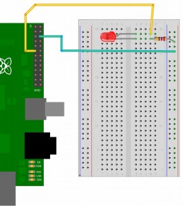
Wiring image:

Then Writing following script:
#!/bin/bash
/root/wiringPi/gpio/gpio mode 0 out
while true then
do
	/root/wiringPi/gpio/gpio write 0 1
	sleep 1
	/root/wiringPi/gpio/gpio write 0 0
	sleep 1
done
Now you will get a shining LED.


