Dec 30, 2013
Technology###Preparation
Mount the partition automatically, add following lines into the /etc/fstab:
/dev/sda3 /media/ntfs ntfs-3g permissions,locale=en_US.utf8 0 2
I decide to use samba to share the files, so I have to install samba
apt-get install samba
The samba server will start automatically, but we have to configure it to adapte to our situation.
Add the configuration to the samba config file:
	/etc/samba/smb.conf
	[raspshare]
	   comment = raspberry PI Share
	   path = /media/ntfs
	   valid users = Trusty
	   public = no
	   writable = yes
	   printable = no
	   create mask = 0765
Restart the samba server
/etc/init.d/samba restart
For using smbpasswd, you have to install samba-common-bin:
apt-get install samba-common-bin
Add some users to the samba sharing:
smbpasswd -a xxx
###Mount the shared partition in client
List all of the available samba shared items:
$ smbclient -L 10.0.0.230 -U%
Then we can mount it, I add following command into the .bashrc, so everytime I enter ‘mountraspsamba’ is ok
alias mountraspsamba='sudo mount -t cifs //10.0.0.230/raspshare/ -o user=xxxx,password=XXXX,workgroup=WORKGROUP /media/raspsamba'
Dec 29, 2013
Technology###连线
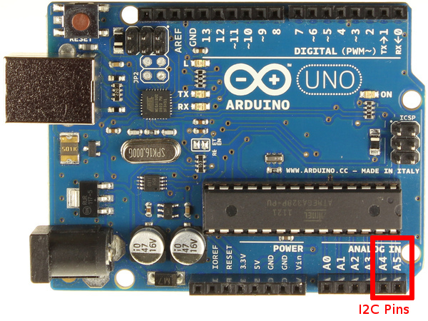
Arduino I2C 连线:
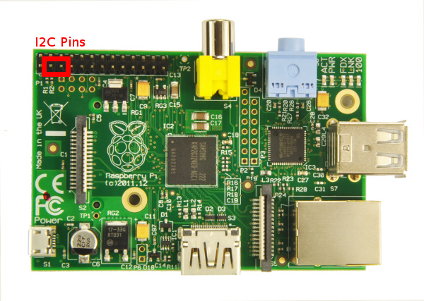
RaspberryPI I2C 连线:
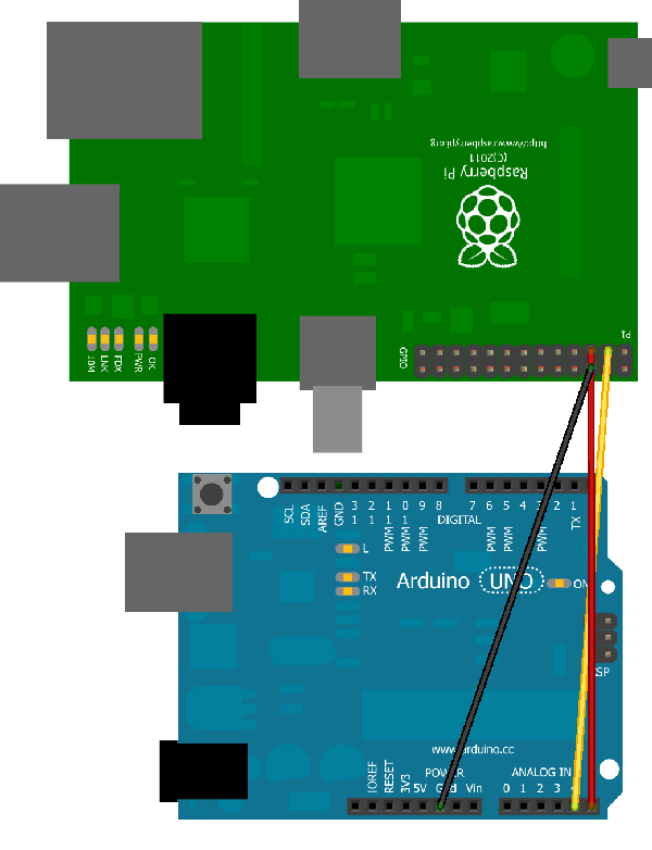
连线图:
	RPI               Arduino (Uno/Duemillanove)
	--------------------------------------------
	GPIO 0 (SDA) <--> Pin 4 (SDA)
	GPIO 1 (SCL) <--> Pin 5 (SCL)
	Ground       <--> Ground
###Arduino端代码
#include <Wire.h>

#define SLAVE_ADDRESS 0x04
int number = 0;
int state = 0;

void setup() {
    pinMode(13, OUTPUT);
    Serial.begin(9600);         // start serial for output
    // initialize i2c as slave
    Wire.begin(SLAVE_ADDRESS);

    // define callbacks for i2c communication
    Wire.onReceive(receiveData);
    Wire.onRequest(sendData);

    Serial.println("Ready!");
}

void loop() {
    delay(100);
}

// callback for received data
void receiveData(int byteCount){

    while(Wire.available()) {
        number = Wire.read();
        Serial.print("data received: ");
        Serial.println(number);

        if (number == 1){

            if (state == 0){
                digitalWrite(13, HIGH); // set the LED on
                state = 1;
            }
            else{
                digitalWrite(13, LOW); // set the LED off
                state = 0;
            }
         }
     }
}

// callback for sending data
void sendData(){
    Wire.write(number);
}
###RaspberryPI端准备
在/etc/modules中增加一行:
i2c-dev
注释掉黑名单:
	$ cat /etc/modprobe.d/raspi-blacklist.conf
	# blacklist spi and i2c by default (many users don't need them)
	# blacklist spi-bcm2708
	#blacklist i2c-bcm2708
安装i2c工具:
apt-get install i2c-tools
安装python库:
apt-get install python-smbus
探测i2c设备
i2cdetect -y 0
如果不是root用户,例如,如果是pi用户,则需要将当前用户增加到i2c组中:
$ sudo adduser pi i2c
###RaspberryPI端代码
import smbus
import time
# for RPI version 1, use "bus = smbus.SMBus(0)"
bus = smbus.SMBus(0)

# This is the address we setup in the Arduino Program
address = 0x04

def writeNumber(value):
    bus.write_byte(address, value)
    # bus.write_byte_data(address, 0, value)
    return -1

def readNumber():
    number = bus.read_byte(address)
    # number = bus.read_byte_data(address, 1)
    return number

while True:
    var = input("Enter 1 - 9: ")
    if not var:
        continue

    writeNumber(var)
    print "RPI: Hi Arduino, I sent you ", var
    # sleep one second
    time.sleep(1)

    number = readNumber()
    print "Arduino: Hey RPI, I received a digit ", number
    print
运行代码时要注意,0~255的数字输入进去,会在arduino i2c slave端收到对应的数据,并原封不动的被返回。超过255的数值将溢出。
Dec 29, 2013
Technology接着上一个日志来,玩一个小tricky,通过SPI总线自己想输入的字符。
主机端,添加下列头文件
#include <string.h>
这使得可以使用strcpy等函数。
重写transfer()函数
static void transfer_mine(int fd, char *buf)
{
	int ret;

	uint8_t tx[140];
	int len = strlen(buf)+1;
	memcpy(tx, buf, strlen(buf)+1);
	tx[strlen(tx)] = '\n';

	uint8_t rx[ARRAY_SIZE(tx)] = {0, };
	struct spi_ioc_transfer tr = {
		.tx_buf = (unsigned long)tx,
		.rx_buf = (unsigned long)rx,
		//.len = ARRAY_SIZE(tx),
		.len = len,
		.delay_usecs = delay,
		.speed_hz = speed,
		.bits_per_word = bits,
	};

	ret = ioctl(fd, SPI_IOC_MESSAGE(1), &tr);
	if (ret < 1)
		pabort("can't send spi message");
}
在main()函数里,改写调用的方式:
	char myinput[140]="Trustywill, Hi, this is Trusty";
	transfer_mine(fd, myinput);
这样就可以将自定义的字符传输过去了,140是随便设置的值,可以设置为别的更大或者更小的值。
当然你也可以从命令行输入想传输的字符, 这里就不深入了。。
Dec 29, 2013
Technology下面是使用SPI在RaspberryPI和Arduino Nano w之间进行双机通信的一个例子。借助它可以很好的理解SPI的工作原理。
###背景知识
RaspberryPI GPIO布局图:

从图中我们可以看到,RaspberryPI上与SPI通信相关的主要是GPIO 10(MOSI), GPIO 9(MISO)和GPIO 11(SCLK).
Arduino布局图:
SPI: 10 (SS), 11 (MOSI), 12 (MISO), 13 (SCK). These pins support SPI communication using the SPI library. SS代表Slava Select.
事实上我们要使用的仅仅是11/12/13三个口而已。
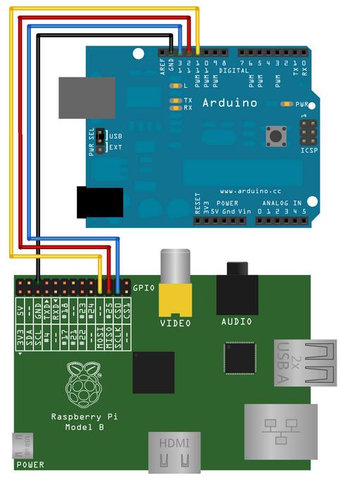
###连线图
如下图进行连线,简单来说,R(10 MOSI)->A(12 MISO), R(9, MISO)->A(11, MOSI), R(11, SCLK) ->A(13, SCK):
 ###Arduino端程序
// Written by Nick Gammon
// February 2011
/**
 * Send arbitrary number of bits at whatever clock rate (tested at 500 KHZ and 500 HZ).
 * This script will capture the SPI bytes, when a '\n' is recieved it will then output
 * the captured byte stream via the serial.
 */

#include <SPI.h>

char buf [100];
volatile byte pos;
volatile boolean process_it;

void setup (void)
{
  Serial.begin (115200);   // debugging

  // have to send on master in, *slave out*
  pinMode(MISO, OUTPUT);

  // turn on SPI in slave mode
  SPCR |= _BV(SPE);
  //SPCR is  Arduino SPI Control Register
  // __BV's definition is like : #define _BV(bit) (1 << (bit))
  // SPE is the register of the SPI Enable

  // get ready for an interrupt
  pos = 0;   // buffer empty
  process_it = false;

  // now turn on interrupts
  SPI.attachInterrupt();

}  // end of setup


// SPI interrupt routine
ISR (SPI_STC_vect)
{
byte c = SPDR;  // grab byte from SPI Data Register

  // add to buffer if room
  if (pos < sizeof buf)
    {
    buf [pos++] = c;

    // example: newline means time to process buffer
    if (c == '\n')
      process_it = true;

    }  // end of room available
}  // end of interrupt routine SPI_STC_vect

// main loop - wait for flag set in interrupt routine
void loop (void)
{
  if (process_it)
    {
    buf [pos] = 0;
    Serial.println (buf);
    pos = 0;
    process_it = false;
    }  // end of flag set

}  // end of loop
Code Walking through:
Arduino SPI Control Register (SPCR), set it to
SPCR |= _BV(SPE);
SPI Data Register (SPDR), SPI数据寄存器。 中断程序中,每次从SPDR中取回一个byte 并存储在c中。
	if (c == '\n')
		process_it = true;
这里通过设置全局变量process_it来影响loop中对接收数据的处理,在loop()中有如下代码段:
	if (process_it)
	{
		//.....
	}
从上面看到,如果process_it为0,则loop中一直在空循环,只有当所有的数据全部接收完毕后,才会一次性打印出所有的数据。在打印完数据后,程序将自动将buf清0, 清0是通过将pos简单置0而实现的,实际的数据其实还在。
###RaspberryPI 端程序
/*
 * SPI testing utility (using spidev driver)
 *
 * Copyright (c) 2007  MontaVista Software, Inc.
 * Copyright (c) 2007  Anton Vorontsov <avorontsov@ru.mvista.com>
 *
 * This program is free software; you can redistribute it and/or modify
 * it under the terms of the GNU General Public License as published by
 * the Free Software Foundation; either version 2 of the License.
 *
 * Cross-compile with cross-gcc -I/path/to/cross-kernel/include
 */

#include <stdint.h>
#include <unistd.h>
#include <stdio.h>
#include <stdlib.h>
#include <getopt.h>
#include <fcntl.h>
#include <sys/ioctl.h>
#include <linux/types.h>
#include <linux/spi/spidev.h>

#define ARRAY_SIZE(a) (sizeof(a) / sizeof((a)[0]))

static void pabort(const char *s)
{
	perror(s);
	abort();
}

static const char *device = "/dev/spidev0.0";
static uint8_t mode;
static uint8_t bits = 8;
static uint32_t speed = 500000;
static uint16_t delay;

static void transfer(int fd)
{
	int ret;
	uint8_t tx[] = {
        0x48, 0x45, 0x4C, 0x4C, 0x4F,
        0x20,
        0x57, 0x4F, 0x52, 0x4C, 0x44,
        0x0A
	};
	uint8_t rx[ARRAY_SIZE(tx)] = {0, };
	struct spi_ioc_transfer tr = {
		.tx_buf = (unsigned long)tx,
		.rx_buf = (unsigned long)rx,
		.len = ARRAY_SIZE(tx),
		.delay_usecs = delay,
		.speed_hz = speed,
		.bits_per_word = bits,
	};

	ret = ioctl(fd, SPI_IOC_MESSAGE(1), &tr);
	if (ret < 1)
		pabort("can't send spi message");

    /*
	for (ret = 0; ret < ARRAY_SIZE(tx); ret++) {
		if (!(ret % 6))
			puts("");
		printf("%.2X ", rx[ret]);
	}
	puts("");
    */
}

static void print_usage(const char *prog)
{
	printf("Usage: %s [-DsbdlHOLC3]\n", prog);
	puts("  -D --device   device to use (default /dev/spidev1.1)\n"
	     "  -s --speed    max speed (Hz)\n"
	     "  -d --delay    delay (usec)\n"
	     "  -b --bpw      bits per word \n"
	     "  -l --loop     loopback\n"
	     "  -H --cpha     clock phase\n"
	     "  -O --cpol     clock polarity\n"
	     "  -L --lsb      least significant bit first\n"
	     "  -C --cs-high  chip select active high\n"
	     "  -3 --3wire    SI/SO signals shared\n");
	exit(1);
}

static void parse_opts(int argc, char *argv[])
{
	while (1) {
		static const struct option lopts[] = {
			{ "device",  1, 0, 'D' },
			{ "speed",   1, 0, 's' },
			{ "delay",   1, 0, 'd' },
			{ "bpw",     1, 0, 'b' },
			{ "loop",    0, 0, 'l' },
			{ "cpha",    0, 0, 'H' },
			{ "cpol",    0, 0, 'O' },
			{ "lsb",     0, 0, 'L' },
			{ "cs-high", 0, 0, 'C' },
			{ "3wire",   0, 0, '3' },
			{ "no-cs",   0, 0, 'N' },
			{ "ready",   0, 0, 'R' },
			{ NULL, 0, 0, 0 },
		};
		int c;

		c = getopt_long(argc, argv, "D:s:d:b:lHOLC3NR", lopts, NULL);

		if (c == -1)
			break;

		switch (c) {
		case 'D':
			device = optarg;
			break;
		case 's':
			speed = atoi(optarg);
			break;
		case 'd':
			delay = atoi(optarg);
			break;
		case 'b':
			bits = atoi(optarg);
			break;
		case 'l':
			mode |= SPI_LOOP;
			break;
		case 'H':
			mode |= SPI_CPHA;
			break;
		case 'O':
			mode |= SPI_CPOL;
			break;
		case 'L':
			mode |= SPI_LSB_FIRST;
			break;
		case 'C':
			mode |= SPI_CS_HIGH;
			break;
		case '3':
			mode |= SPI_3WIRE;
			break;
		case 'N':
			mode |= SPI_NO_CS;
			break;
		case 'R':
			mode |= SPI_READY;
			break;
		default:
			print_usage(argv[0]);
			break;
		}
	}
}

int main(int argc, char *argv[])
{
	int ret = 0;
	int fd;

	parse_opts(argc, argv);

	fd = open(device, O_RDWR);
	if (fd < 0)
		pabort("can't open device");

	/*
	 * spi mode
	 */
	ret = ioctl(fd, SPI_IOC_WR_MODE, &mode);
	if (ret == -1)
		pabort("can't set spi mode");

	ret = ioctl(fd, SPI_IOC_RD_MODE, &mode);
	if (ret == -1)
		pabort("can't get spi mode");

	/*
	 * bits per word
	 */
	ret = ioctl(fd, SPI_IOC_WR_BITS_PER_WORD, &bits);
	if (ret == -1)
		pabort("can't set bits per word");

	ret = ioctl(fd, SPI_IOC_RD_BITS_PER_WORD, &bits);
	if (ret == -1)
		pabort("can't get bits per word");

	/*
	 * max speed hz
	 */
	ret = ioctl(fd, SPI_IOC_WR_MAX_SPEED_HZ, &speed);
	if (ret == -1)
		pabort("can't set max speed hz");

	ret = ioctl(fd, SPI_IOC_RD_MAX_SPEED_HZ, &speed);
	if (ret == -1)
		pabort("can't get max speed hz");

	printf("spi mode: %d\n", mode);
	printf("bits per word: %d\n", bits);
	printf("max speed: %d Hz (%d KHz)\n", speed, speed/1000);

	transfer(fd);

	close(fd);

	return ret;
}
解析: 在main()函数中,设置完spi总线的相关参数后,调用transfer(fd)来传递参数。
transfer()函数的实现如下:
static void transfer(int fd)
{
	int ret;
	uint8_t tx[] = {
        0x48, 0x45, 0x4C, 0x4C, 0x4F,
        0x20,
        0x57, 0x4F, 0x52, 0x4C, 0x44,
        0x0A
	};
	uint8_t rx[ARRAY_SIZE(tx)] = {0, };
	struct spi_ioc_transfer tr = {
		.tx_buf = (unsigned long)tx,
		.rx_buf = (unsigned long)rx,
		.len = ARRAY_SIZE(tx),
		.delay_usecs = delay,
		.speed_hz = speed,
		.bits_per_word = bits,
	};

	ret = ioctl(fd, SPI_IOC_MESSAGE(1), &tr);
	if (ret < 1)
		pabort("can't send spi message");

    /*
	for (ret = 0; ret < ARRAY_SIZE(tx); ret++) {
		if (!(ret % 6))
			puts("");
		printf("%.2X ", rx[ret]);
	}
	puts("");
    */
}
tx即为字符串,‘H'=0x48, ‘E'=0x45, ‘L'=0x4c, ‘L'=0x4c, ‘O'=0x4f, ' ‘=0x20, ‘W'=0x57, ‘O'=0x4f, ‘R'=0x52, ‘L'=0x4c, ‘D'=0x44, ‘\n'=0x0a.
实际传送则是调用:
ret = ioctl(fd, SPI_IOC_MESSAGE(1), &tr);
有关它的解释如下:
	SPI_IOC_MESSAGE gives userspace the equivalent of kernel spi_sync().
	  72 * Pass it an array of related transfers, they'll execute together.
	  73 * Each transfer may be half duplex (either direction) or full duplex.
	  74 *
	  75 *      struct spi_ioc_transfer mesg[4];
	  76 *      ...
	  77 *      status = ioctl(fd, SPI_IOC_MESSAGE(4), mesg);

	#define SPI_IOC_MESSAGE(N) _IOW(SPI_IOC_MAGIC, 0, char[SPI_MSGSIZE(N)])
调用完transfer()函数后,调用close()来关闭文件描述符。
Dec 28, 2013
Technology###Introduction
The detailed information could be seen as in :
http://www.eefocus.com/zhang700309/blog/13-08/296390_6c438.html
###Wiring:
Notice we use the interrupt 1.
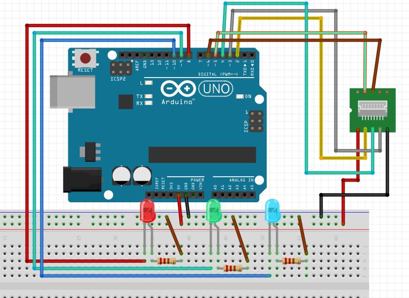 ###Code
#include <TimerOne.h>

#define S0     6   // Please notice the Pin's define
#define S1     5
#define S2     4
#define S3     2
#define OUT    3

int   g_count = 0;    // count the frequecy
int   g_array[3];     // store the RGB value
int   g_flag = 0;     // filter of RGB queue
float g_SF[3];        // save the RGB Scale factor


// Init TSC230 and setting Frequency.
void TSC_Init()
{
  pinMode(S0, OUTPUT);
  pinMode(S1, OUTPUT);
  pinMode(S2, OUTPUT);
  pinMode(S3, OUTPUT);
  pinMode(OUT, INPUT);

  digitalWrite(S0, LOW);  // OUTPUT FREQUENCY SCALING 2%
  digitalWrite(S1, HIGH);
}

// Select the filter color
void TSC_FilterColor(int Level01, int Level02)
{
  if(Level01 != 0)
    Level01 = HIGH;

  if(Level02 != 0)
    Level02 = HIGH;

  digitalWrite(S2, Level01);
  digitalWrite(S3, Level02);
}

void TSC_Count()
{
  g_count ++ ;
}

void TSC_Callback()
{
  switch(g_flag)
  {
    case 0:
         Serial.println("->WB Start");
         TSC_WB(LOW, LOW);              //Filter without Red
         break;
    case 1:
         Serial.print("->Frequency R=");
         Serial.println(g_count);
         g_array[0] = g_count;
         TSC_WB(HIGH, HIGH);            //Filter without Green
         break;
    case 2:
         Serial.print("->Frequency G=");
         Serial.println(g_count);
         g_array[1] = g_count;
         TSC_WB(LOW, HIGH);             //Filter without Blue
         break;

    case 3:
         Serial.print("->Frequency B=");
         Serial.println(g_count);
         Serial.println("->WB End");
         g_array[2] = g_count;
         TSC_WB(HIGH, LOW);             //Clear(no filter)
         break;
   default:
         g_count = 0;
         break;
  }
}

void TSC_WB(int Level0, int Level1)      //White Balance
{
  g_count = 0;
  g_flag ++;
  TSC_FilterColor(Level0, Level1);
  Timer1.setPeriod(1000000);             // set 1s period
}

void setup()
{
  TSC_Init();
  Serial.begin(9600);
  Timer1.initialize();             // defaulte is 1s
  Timer1.attachInterrupt(TSC_Callback);
  attachInterrupt(1, TSC_Count, RISING);
 pinMode(8, OUTPUT);
 pinMode(9, OUTPUT);
 pinMode(10, OUTPUT);
 digitalWrite(8,HIGH);
 digitalWrite(9,HIGH);
 digitalWrite(10,HIGH);

  delay(4000);

  for(int i=0; i<3; i++)
    Serial.println(g_array[i]);

  g_SF[0] = 255.0/ g_array[0];     //R Scale factor
  g_SF[1] = 255.0/ g_array[1] ;    //G Scale factor
  g_SF[2] = 255.0/ g_array[2] ;    //B Scale factor

  Serial.println(g_SF[0]);
  Serial.println(g_SF[1]);
  Serial.println(g_SF[2]);

}

void loop()
{
   g_flag = 0;
   for(int i=0; i<3; i++)
    Serial.println(int(g_array[i] * g_SF[i]));
   if(((g_array[0]*g_SF[0])>(g_array[1]*g_SF[1])) && ((g_array[0]*g_SF[0])>(g_array[2]*g_SF[2])))
   {
      digitalWrite(8,HIGH);
      digitalWrite(9,LOW);
      digitalWrite(10,LOW);
   }
   else if(((g_array[1]*g_SF[1])>(g_array[0]*g_SF[0])) && ((g_array[1]*g_SF[1])>(g_array[2]*g_SF[2])))
   {
      digitalWrite(8,LOW);
      digitalWrite(9,HIGH);
      digitalWrite(10,LOW);
   }
   else if(((g_array[2]*g_SF[2])>(g_array[1]*g_SF[1])) && ((g_array[2]*g_SF[2])>(g_array[0]*g_SF[0])))
   {
      digitalWrite(8,LOW);
      digitalWrite(9,LOW);
      digitalWrite(10,HIGH);
   }
   else
   {
      digitalWrite(8,LOW);
      digitalWrite(9,LOW);
      digitalWrite(10,LOW);
   }
   delay(4000);

}
###Effect
First, the program will caculate the RBG base value out.
If you put the sensor on a red object, red LED will be lighten, turn the sensor facing a green object, green LED will be lighten; blue object for blue LED.