SPI连接raspberryPI和Arduino

下面是使用SPI在RaspberryPI和Arduino Nano w之间进行双机通信的一个例子。借助它可以很好的理解SPI的工作原理。
###背景知识 RaspberryPI GPIO布局图:
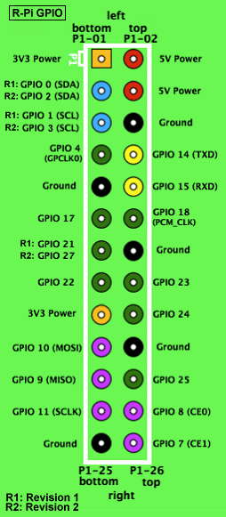
/images/GPIOs.png
从图中我们可以看到,RaspberryPI上与SPI通信相关的主要是GPIO 10(MOSI), GPIO 9(MISO)和GPIO 11(SCLK).
Arduino布局图:
SPI: 10 (SS), 11 (MOSI), 12 (MISO), 13 (SCK). These pins support SPI communication using the SPI library. SS代表Slava Select.
事实上我们要使用的仅仅是11/12/13三个口而已。
###连线图 如下图进行连线,简单来说,R(10 MOSI)->A(12 MISO), R(9, MISO)->A(11, MOSI), R(11, SCLK) ->A(13, SCK):
/images/spiconnector.jpg ###Arduino端程序

// Written by Nick Gammon
// February 2011
/**
 * Send arbitrary number of bits at whatever clock rate (tested at 500 KHZ and 500 HZ).
 * This script will capture the SPI bytes, when a '\n' is recieved it will then output
 * the captured byte stream via the serial.
 */
 
#include <SPI.h>
 
char buf [100];
volatile byte pos;
volatile boolean process_it;
 
void setup (void)
{
  Serial.begin (115200);   // debugging
 
  // have to send on master in, *slave out*
  pinMode(MISO, OUTPUT);
  
  // turn on SPI in slave mode
  SPCR |= _BV(SPE);
  //SPCR is  Arduino SPI Control Register
  // __BV's definition is like : #define _BV(bit) (1 << (bit))
  // SPE is the register of the SPI Enable
  
  // get ready for an interrupt 
  pos = 0;   // buffer empty
  process_it = false;
 
  // now turn on interrupts
  SPI.attachInterrupt();
 
}  // end of setup
 
 
// SPI interrupt routine
ISR (SPI_STC_vect)
{
byte c = SPDR;  // grab byte from SPI Data Register
  
  // add to buffer if room
  if (pos < sizeof buf)
    {
    buf [pos++] = c;
    
    // example: newline means time to process buffer
    if (c == '\n')
      process_it = true;
      
    }  // end of room available
}  // end of interrupt routine SPI_STC_vect
 
// main loop - wait for flag set in interrupt routine
void loop (void)
{
  if (process_it)
    {
    buf [pos] = 0;  
    Serial.println (buf);
    pos = 0;
    process_it = false;
    }  // end of flag set
    
}  // end of loop

Code Walking through:
Arduino SPI Control Register (SPCR), set it to

	SPCR |= _BV(SPE);

SPI Data Register (SPDR), SPI数据寄存器。 中断程序中,每次从SPDR中取回一个byte 并存储在c中。

	if (c == '\n')
		process_it = true;

这里通过设置全局变量process_it来影响loop中对接收数据的处理,在loop()中有如下代码段:

	if (process_it)
	{
		//.....
	}

从上面看到,如果process_it为0,则loop中一直在空循环,只有当所有的数据全部接收完毕后,才会一次性打印出所有的数据。在打印完数据后,程序将自动将buf清0, 清0是通过将pos简单置0而实现的,实际的数据其实还在。 ###RaspberryPI 端程序

/*
 * SPI testing utility (using spidev driver)
 *
 * Copyright (c) 2007  MontaVista Software, Inc.
 * Copyright (c) 2007  Anton Vorontsov <avorontsov@ru.mvista.com>
 *
 * This program is free software; you can redistribute it and/or modify
 * it under the terms of the GNU General Public License as published by
 * the Free Software Foundation; either version 2 of the License.
 *
 * Cross-compile with cross-gcc -I/path/to/cross-kernel/include
 */
 
#include <stdint.h>
#include <unistd.h>
#include <stdio.h>
#include <stdlib.h>
#include <getopt.h>
#include <fcntl.h>
#include <sys/ioctl.h>
#include <linux/types.h>
#include <linux/spi/spidev.h>
 
#define ARRAY_SIZE(a) (sizeof(a) / sizeof((a)[0]))
 
static void pabort(const char *s)
{
	perror(s);
	abort();
}
 
static const char *device = "/dev/spidev0.0";
static uint8_t mode;
static uint8_t bits = 8;
static uint32_t speed = 500000;
static uint16_t delay;
 
static void transfer(int fd)
{
	int ret;
	uint8_t tx[] = {
        0x48, 0x45, 0x4C, 0x4C, 0x4F,
        0x20, 
        0x57, 0x4F, 0x52, 0x4C, 0x44,
        0x0A 
	};
	uint8_t rx[ARRAY_SIZE(tx)] = {0, };
	struct spi_ioc_transfer tr = {
		.tx_buf = (unsigned long)tx,
		.rx_buf = (unsigned long)rx,
		.len = ARRAY_SIZE(tx),
		.delay_usecs = delay,
		.speed_hz = speed,
		.bits_per_word = bits,
	};
 
	ret = ioctl(fd, SPI_IOC_MESSAGE(1), &tr);
	if (ret < 1)
		pabort("can't send spi message");
 
    /*
	for (ret = 0; ret < ARRAY_SIZE(tx); ret++) {
		if (!(ret % 6))
			puts("");
		printf("%.2X ", rx[ret]);
	}
	puts("");
    */
}
 
static void print_usage(const char *prog)
{
	printf("Usage: %s [-DsbdlHOLC3]\n", prog);
	puts("  -D --device   device to use (default /dev/spidev1.1)\n"
	     "  -s --speed    max speed (Hz)\n"
	     "  -d --delay    delay (usec)\n"
	     "  -b --bpw      bits per word \n"
	     "  -l --loop     loopback\n"
	     "  -H --cpha     clock phase\n"
	     "  -O --cpol     clock polarity\n"
	     "  -L --lsb      least significant bit first\n"
	     "  -C --cs-high  chip select active high\n"
	     "  -3 --3wire    SI/SO signals shared\n");
	exit(1);
}
 
static void parse_opts(int argc, char *argv[])
{
	while (1) {
		static const struct option lopts[] = {
			{ "device",  1, 0, 'D' },
			{ "speed",   1, 0, 's' },
			{ "delay",   1, 0, 'd' },
			{ "bpw",     1, 0, 'b' },
			{ "loop",    0, 0, 'l' },
			{ "cpha",    0, 0, 'H' },
			{ "cpol",    0, 0, 'O' },
			{ "lsb",     0, 0, 'L' },
			{ "cs-high", 0, 0, 'C' },
			{ "3wire",   0, 0, '3' },
			{ "no-cs",   0, 0, 'N' },
			{ "ready",   0, 0, 'R' },
			{ NULL, 0, 0, 0 },
		};
		int c;
 
		c = getopt_long(argc, argv, "D:s:d:b:lHOLC3NR", lopts, NULL);
 
		if (c == -1)
			break;
 
		switch (c) {
		case 'D':
			device = optarg;
			break;
		case 's':
			speed = atoi(optarg);
			break;
		case 'd':
			delay = atoi(optarg);
			break;
		case 'b':
			bits = atoi(optarg);
			break;
		case 'l':
			mode |= SPI_LOOP;
			break;
		case 'H':
			mode |= SPI_CPHA;
			break;
		case 'O':
			mode |= SPI_CPOL;
			break;
		case 'L':
			mode |= SPI_LSB_FIRST;
			break;
		case 'C':
			mode |= SPI_CS_HIGH;
			break;
		case '3':
			mode |= SPI_3WIRE;
			break;
		case 'N':
			mode |= SPI_NO_CS;
			break;
		case 'R':
			mode |= SPI_READY;
			break;
		default:
			print_usage(argv[0]);
			break;
		}
	}
}
 
int main(int argc, char *argv[])
{
	int ret = 0;
	int fd;
 
	parse_opts(argc, argv);
 
	fd = open(device, O_RDWR);
	if (fd < 0)
		pabort("can't open device");
 
	/*
	 * spi mode
	 */
	ret = ioctl(fd, SPI_IOC_WR_MODE, &mode);
	if (ret == -1)
		pabort("can't set spi mode");
 
	ret = ioctl(fd, SPI_IOC_RD_MODE, &mode);
	if (ret == -1)
		pabort("can't get spi mode");
 
	/*
	 * bits per word
	 */
	ret = ioctl(fd, SPI_IOC_WR_BITS_PER_WORD, &bits);
	if (ret == -1)
		pabort("can't set bits per word");
 
	ret = ioctl(fd, SPI_IOC_RD_BITS_PER_WORD, &bits);
	if (ret == -1)
		pabort("can't get bits per word");
 
	/*
	 * max speed hz
	 */
	ret = ioctl(fd, SPI_IOC_WR_MAX_SPEED_HZ, &speed);
	if (ret == -1)
		pabort("can't set max speed hz");
 
	ret = ioctl(fd, SPI_IOC_RD_MAX_SPEED_HZ, &speed);
	if (ret == -1)
		pabort("can't get max speed hz");
 
	printf("spi mode: %d\n", mode);
	printf("bits per word: %d\n", bits);
	printf("max speed: %d Hz (%d KHz)\n", speed, speed/1000);
 
	transfer(fd);
 
	close(fd);
 
	return ret;
}

解析: 在main()函数中,设置完spi总线的相关参数后,调用transfer(fd)来传递参数。
transfer()函数的实现如下:

static void transfer(int fd)
{
	int ret;
	uint8_t tx[] = {
        0x48, 0x45, 0x4C, 0x4C, 0x4F,
        0x20, 
        0x57, 0x4F, 0x52, 0x4C, 0x44,
        0x0A 
	};
	uint8_t rx[ARRAY_SIZE(tx)] = {0, };
	struct spi_ioc_transfer tr = {
		.tx_buf = (unsigned long)tx,
		.rx_buf = (unsigned long)rx,
		.len = ARRAY_SIZE(tx),
		.delay_usecs = delay,
		.speed_hz = speed,
		.bits_per_word = bits,
	};
 
	ret = ioctl(fd, SPI_IOC_MESSAGE(1), &tr);
	if (ret < 1)
		pabort("can't send spi message");
 
    /*
	for (ret = 0; ret < ARRAY_SIZE(tx); ret++) {
		if (!(ret % 6))
			puts("");
		printf("%.2X ", rx[ret]);
	}
	puts("");
    */
}

tx即为字符串,‘H'=0x48, ‘E'=0x45, ‘L'=0x4c, ‘L'=0x4c, ‘O'=0x4f, ' ‘=0x20, ‘W'=0x57, ‘O'=0x4f, ‘R'=0x52, ‘L'=0x4c, ‘D'=0x44, ‘\n'=0x0a.
实际传送则是调用: ret = ioctl(fd, SPI_IOC_MESSAGE(1), &tr); 有关它的解释如下:

	SPI_IOC_MESSAGE gives userspace the equivalent of kernel spi_sync().
	  72 * Pass it an array of related transfers, they'll execute together.
	  73 * Each transfer may be half duplex (either direction) or full duplex.
	  74 *
	  75 *      struct spi_ioc_transfer mesg[4];
	  76 *      ...
	  77 *      status = ioctl(fd, SPI_IOC_MESSAGE(4), mesg);

	#define SPI_IOC_MESSAGE(N) _IOW(SPI_IOC_MAGIC, 0, char[SPI_MSGSIZE(N)])

调用完transfer()函数后,调用close()来关闭文件描述符。

TSC3200 on Arduino

###Introduction The detailed information could be seen as in :
http://www.eefocus.com/zhang700309/blog/13-08/296390_6c438.html
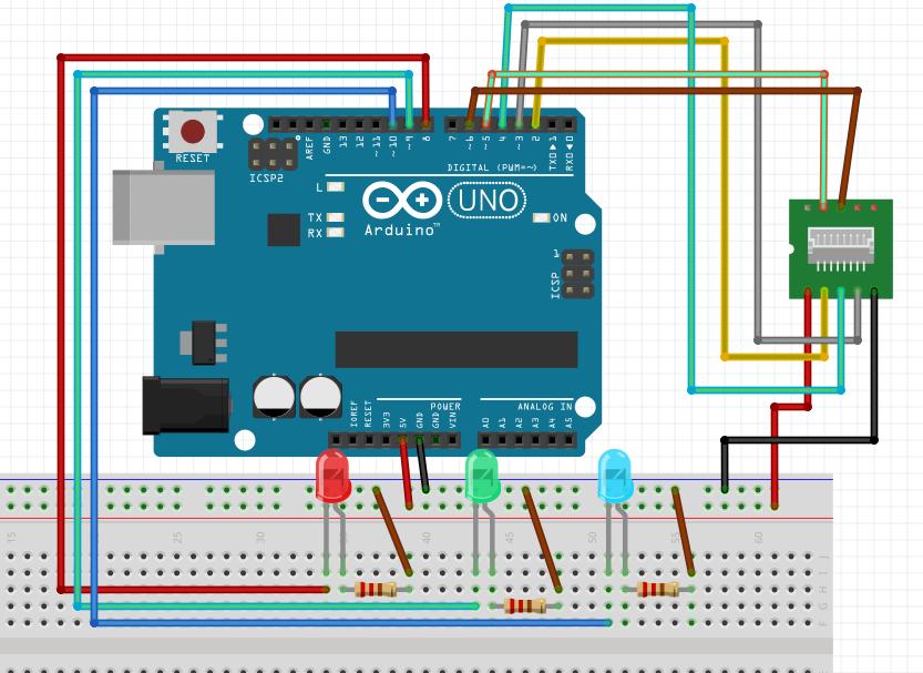
###Wiring: Notice we use the interrupt 1.
images/tsc3200d.jpg ###Code

#include <TimerOne.h>
 
#define S0     6   // Please notice the Pin's define
#define S1     5
#define S2     4
#define S3     2
#define OUT    3
 
int   g_count = 0;    // count the frequecy
int   g_array[3];     // store the RGB value
int   g_flag = 0;     // filter of RGB queue
float g_SF[3];        // save the RGB Scale factor
 
 
// Init TSC230 and setting Frequency.
void TSC_Init()
{
  pinMode(S0, OUTPUT);
  pinMode(S1, OUTPUT);
  pinMode(S2, OUTPUT);
  pinMode(S3, OUTPUT);
  pinMode(OUT, INPUT);
 
  digitalWrite(S0, LOW);  // OUTPUT FREQUENCY SCALING 2%
  digitalWrite(S1, HIGH); 
}
 
// Select the filter color 
void TSC_FilterColor(int Level01, int Level02)
{
  if(Level01 != 0)
    Level01 = HIGH;
 
  if(Level02 != 0)
    Level02 = HIGH;
 
  digitalWrite(S2, Level01); 
  digitalWrite(S3, Level02); 
}
 
void TSC_Count()
{
  g_count ++ ;
}
 
void TSC_Callback()
{
  switch(g_flag)
  {
    case 0: 
         Serial.println("->WB Start");
         TSC_WB(LOW, LOW);              //Filter without Red
         break;
    case 1:
         Serial.print("->Frequency R=");
         Serial.println(g_count);
         g_array[0] = g_count;
         TSC_WB(HIGH, HIGH);            //Filter without Green
         break;
    case 2:
         Serial.print("->Frequency G=");
         Serial.println(g_count);
         g_array[1] = g_count;
         TSC_WB(LOW, HIGH);             //Filter without Blue
         break;
 
    case 3:
         Serial.print("->Frequency B=");
         Serial.println(g_count);
         Serial.println("->WB End");
         g_array[2] = g_count;
         TSC_WB(HIGH, LOW);             //Clear(no filter)   
         break;
   default:
         g_count = 0;
         break;
  }
}
 
void TSC_WB(int Level0, int Level1)      //White Balance
{
  g_count = 0;
  g_flag ++;
  TSC_FilterColor(Level0, Level1);
  Timer1.setPeriod(1000000);             // set 1s period
}
 
void setup()
{
  TSC_Init();
  Serial.begin(9600);
  Timer1.initialize();             // defaulte is 1s
  Timer1.attachInterrupt(TSC_Callback);  
  attachInterrupt(1, TSC_Count, RISING);  
 pinMode(8, OUTPUT);
 pinMode(9, OUTPUT);
 pinMode(10, OUTPUT);
 digitalWrite(8,HIGH);
 digitalWrite(9,HIGH);
 digitalWrite(10,HIGH);
 
  delay(4000);
 
  for(int i=0; i<3; i++)
    Serial.println(g_array[i]);
 
  g_SF[0] = 255.0/ g_array[0];     //R Scale factor
  g_SF[1] = 255.0/ g_array[1] ;    //G Scale factor
  g_SF[2] = 255.0/ g_array[2] ;    //B Scale factor
 
  Serial.println(g_SF[0]);
  Serial.println(g_SF[1]);
  Serial.println(g_SF[2]);
 
}
 
void loop()
{
   g_flag = 0;
   for(int i=0; i<3; i++)
    Serial.println(int(g_array[i] * g_SF[i]));
   if(((g_array[0]*g_SF[0])>(g_array[1]*g_SF[1])) && ((g_array[0]*g_SF[0])>(g_array[2]*g_SF[2])))
   {
      digitalWrite(8,HIGH);
      digitalWrite(9,LOW);
      digitalWrite(10,LOW);
   }
   else if(((g_array[1]*g_SF[1])>(g_array[0]*g_SF[0])) && ((g_array[1]*g_SF[1])>(g_array[2]*g_SF[2])))
   {
      digitalWrite(8,LOW);
      digitalWrite(9,HIGH);
      digitalWrite(10,LOW);
   }     
   else if(((g_array[2]*g_SF[2])>(g_array[1]*g_SF[1])) && ((g_array[2]*g_SF[2])>(g_array[0]*g_SF[0])))
   {
      digitalWrite(8,LOW);
      digitalWrite(9,LOW);
      digitalWrite(10,HIGH);
   }        
   else
   {
      digitalWrite(8,LOW);
      digitalWrite(9,LOW);
      digitalWrite(10,LOW);
   }
   delay(4000);
 
}

###Effect First, the program will caculate the RBG base value out.
If you put the sensor on a red object, red LED will be lighten, turn the sensor facing a green object, green LED will be lighten; blue object for blue LED.

使用超声波传感器控制LED

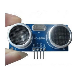
###Wiring Pictures The UltraSound sensor is like following picture, it only sold at 8RMB on Taobao:
ultraintaobao.jpg
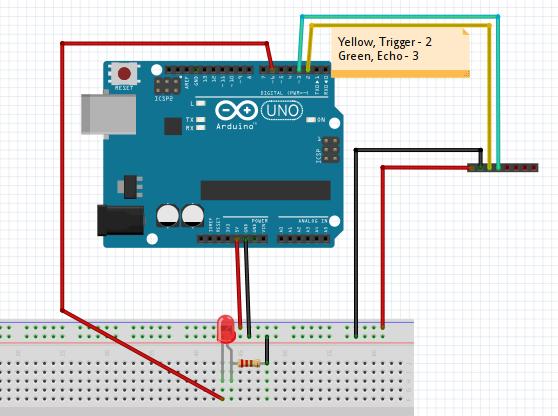
The Wiring Pictures is listed as following:
/images/UltraSound.jpg ###Working Principle Trigger Pin will emit the ultra-sound, then Echo Pin will receive the reflected ultra-sound. Calculate its fleeting time then plus the speed of sound we can get the distance.
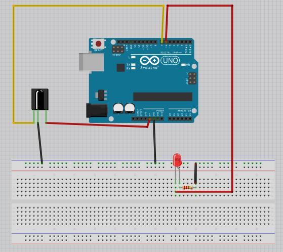
So the working method is:
a. Trig pin emmit a high signal out.
b. Echo pin will wait for receiving the high signal.
c. Calculate the fleeting time.
###The code

const int TrigPin = 2; 
const int EchoPin = 3; 
const int LedPin = 6;

float cm; 

int reverseStatus = 0;
int ledstatus = HIGH;

void setup() 
{ 
Serial.begin(9600); 
pinMode(TrigPin, OUTPUT); 
pinMode(EchoPin, INPUT); 
pinMode(LedPin, OUTPUT);
digitalWrite(LedPin, HIGH);
} 
void loop() 
{ 
digitalWrite(TrigPin, LOW); //低高低电平发一个短时间脉冲去TrigPin 
delayMicroseconds(2); 
digitalWrite(TrigPin, HIGH); 
delayMicroseconds(10); 
digitalWrite(TrigPin, LOW);
cm = pulseIn(EchoPin, HIGH) / 58.0; //将回波时间换算成cm 
cm = (int(cm * 100.0)) / 100.0; //保留两位小数 
if( cm < 10 )
{
  reverseStatus = 1;
}
else
{
  reverseStatus = 0;
}
if(reverseStatus == 1)
{
  if(ledstatus == LOW)
  {
    digitalWrite(LedPin, HIGH);
    ledstatus = HIGH;
  }
  else if(ledstatus == HIGH)
  {
    digitalWrite(LedPin, LOW);
    ledstatus = LOW;
  }
}
Serial.print(cm); 
Serial.print("cm"); 
Serial.println(); 
delay(1000); 
} 

###Critical Code Walk-through

digitalWrite(TrigPin, LOW); //低高低电平发一个短时间脉冲去TrigPin 
delayMicroseconds(2); 
digitalWrite(TrigPin, HIGH); 
delayMicroseconds(10); 
digitalWrite(TrigPin, LOW);
cm = pulseIn(EchoPin, HIGH) / 58.0; //将回波时间换算成cm 
cm = (int(cm * 100.0)) / 100.0; //保留两位小数 

First write low, delay 2 microsecond, then write high, continue for 10 microsecond, then switch to low.
pulseIn() will return the time wait the pin switch to High signal. Its output is microseconds. Since the speed of sound is 340m/s, like the following functions:

long microsecondsToCentimeters(long microseconds)
{
// The speed of sound is 340 m/s or 29 microseconds per centimeter.
// The ping travels out and back, so to find the distance of the
// object we take half of the distance travelled.
return microseconds / 29 / 2;
}

the distance we can caculate like: the time is x microseconds, while in 1 microseconds, the sound can walk:
340m/s = 340x100cm/s = 34cm/ms, so the distance will be:
distance == xms x 34cm/ms /2 == xms x 17
Thus the code could alter to :

  //cm = pulseIn(EchoPin, HIGH) / 58.0; //将回波时间换算成cm 
  cm = pulseIn(EchoPin, HIGH) * 17 / 1000;

Both are OK for detecting the distance.
###Effect When you hold your hands or other object to the ultrasound in less than 10cm, the led status will be changed in 1 seconds.

HC-SR501人体感应模块 &amp; Arduino

###连线图 led – pin 6, SR501 pin 7.
/images/wiring1.jpg ###代码

//红外感应
//信号接 7 端口
//LED will be 6 port
int sigpin = 7;
int ledpin = 6;
 
void setup()
{
  pinMode(sigpin, INPUT);
  pinMode(ledpin, OUTPUT);
  digitalWrite(ledpin, HIGH);
  
  Serial.begin(9600);  // 打开串口,设置波特率为9600 bps
}
 
int storefun = 0;
int ledstatus = HIGH;

void loop()
{
  int in = digitalRead(sigpin); 
  
  
  //Change the led ON/OFF accoriding to the status sensor
  if(in != storefun)
  {
    Serial.println("They are not equal!");
    if(ledstatus == LOW)
    {
      digitalWrite(ledpin,HIGH);
      ledstatus = HIGH;
    }
    else if(ledstatus == HIGH)
    {
      digitalWrite(ledpin, LOW);
      ledstatus = LOW;
    }
  }
  storefun = in; 
  Serial.println(in); //有人的时候输出高电平1 无人0
  Serial.println(storefun);
  Serial.println("***");
  delay(2000);    
}

ArchLinux中文化问题

本文将涉及到ArchLinux下中文化问题,主要是关于终端字符和vim中代码格式的细调工作。
###Vim 配置 ####Colorscheme配置:
下载几个美观的主题: solarized: https://github.com/altercation/vim-colors-solarized
molokai: https://github.com/tomasr/molokai
phd: http://www.vim.org/scripts/script.php?script_id=3139
将其解压开后,拷贝到~/.vim/colors,然后修改~/.vimrc:

	set background=dark
	"set background=bright
	"colorscheme solarized
	colorscheme molokai

####Vim字体配置:
Consolas是一种专门为编程人员设计的字体,这一字体的特性是所有字母、数字与符号均能非常容易辨认,而且所有字符都具有相同的宽度,让编人员看着更舒服。但我们用Consolas在显示程序源码时,不可避免要使用中文注释。而Consolas不支持中文,因此中文默认是使用宋体显示的。当使用10点大小的时候,中文就模糊不清了。如果采用斜体显示注释的话,宋体就更加显得支离破碎。
在中文显示上,雅黑字体确实不错,但雅黑不是等宽字体,不能用于源码显示。
使用字体工具将雅黑和Consolas集成在一起后,程序员就可以在Linux环境下的源码中看到优秀的中文显示效果。
下载地址在 :
http://dl.dbank.com/c01bo3a1eo

https://code.google.com/p/uigroupcode/downloads/detail?name=YaHei.Consolas.1.12.zip&can=2&q=

解压缩后,运行以下命令:

	sudo mkdir -p /usr/share/fonts/vista
	sudo cp YaHei.Consolas.1.12.ttf /usr/share/fonts/vista/

更改权限:

	sudo chmod 644 /usr/share/fonts/vista/*.ttf

安装字体:

	cd /usr/share/fonts/vista/
	sudo mkfontscale
	sudo mkfontdir
	sudo fc-cache -fv

###终端字体配置 更改终端模拟器的字体为Yahei Consolas Hybrid即可 gvim中字体设置:

	set guifont=YaHei\ Consolas\ Hybrid\ 11.5

其他的vim细调:

	set cursorline  "光标线
	set cursorcolumn  "竖线

最后效果如下:
/images/effect.jpg

Konsole Setup

Since konsole’s QT don’t think YaHei Consolas is the fonts, we need manually specify its configuration:

$ cat ~/.kde/share/apps/konsole/Shell.profile
[Appearance]
ColorScheme=Linux
- Font=Monospace,13,-1,2,50,0,0,0,0,0
+ Font=YaHei Consolas Hybrid,11,-1,5,50,0,0,0,0,0

Then you should close all of the opened konsoles, re-launch the konsole and you will get the beautiful views of the new fonts.

In 2015 Aug30, the configuration is changed to:

# vim $HOME/.local/share/konsole/Shell.profile
+ Font=YaHei Consolas Hybrid,11,-1,5,50,0,0,0,0,0