Oct 29, 2014
TechnologyProgram Storage
Classical Blink program:
/*
  Blink
  Turns on an LED on for one second, then off for one second, repeatedly.

  Most Arduinos have an on-board LED you can control. On the Uno and
  Leonardo, it is attached to digital pin 13. If you're unsure what
  pin the on-board LED is connected to on your Arduino model, check
  the documentation at http://arduino.cc

  This example code is in the public domain.

  modified 8 May 2014
  by Scott Fitzgerald
 */


// the setup function runs once when you press reset or power the board
void setup() {
  // initialize digital pin 13 as an output.
  pinMode(13, OUTPUT);
}

// the loop function runs over and over again forever
void loop() {
  digitalWrite(13, HIGH);   // turn the LED on (HIGH is the voltage level)
  delay(1000);              // wait for a second
  digitalWrite(13, LOW);    // turn the LED off by making the voltage LOW
  delay(1000);              // wait for a second
}
Compilation size:
Binary sketch size: 1,082 bytes (of a 32,256 byte maximum)
Comment the pinMode(13, OUTPUT), then the compilation size would be:
Binary sketch size: 948 bytes (of a 32,256 byte maximum)
Since PB5 is the output pin for 13, One command for replacing pinMode():
void setup() {
  // initialize digital pin 13 as an output.
  //pinMode(13, OUTPUT);
  bitSet(DDRB, 5);
}
Further:
void loop() {
  //digitalWrite(13, HIGH);   // turn the LED on (HIGH is the voltage level)
  bitSet(PINB, 5);
  delay(1000);              // wait for a second
  //digitalWrite(13, LOW);    // turn the LED off by making the voltage LOW
  bitSet(PINB, 5);
  delay(1000);              // wait for a second
}
Binary sketch size: 680 bytes (of a 32,256 byte maximum)
Use bitSet() for reverse the bit, then the size will greatly reduced.
Further reduction will consider replace the delay(1000) with an empty for() loop, which is listed as following:
  //delay(1000);              // wait for a second
  for (int i=0; i<32000; i++);
The binary size is:
Binary sketch size: 478 bytes (of a 32,256 byte maximum)
We could add following declaration:
for (volatile int i=0; i<32000; i++);
Serial Communication
Origin serial communication source code:
void setup()
{
  Serial.begin(9600);
  Serial.println("Hello World!");
}

void loop()
{
  // Do Nothing.
}
Size is:
Binary sketch size: 2,034 bytes (of a 32,256 byte maximum)
Remove all of the functionality, then the size is:
Binary sketch size: 472 bytes (of a 32,256 byte maximum)
Directly manuplate the serial port hardware:
#define BAUD_RATE 9600
#define BAUD_RATE_DIVISOR (F_CPU/16/BAUD_RATE -1 )

void usart_putc(char c)
{
  loop_until_bit_is_set(UCSR0A, UDRE0);
  UDR0 = c;
}

void setup()
{
  //Serial.begin(9600);
  //Serial.println("Hello World!");
  UCSR0A = 0;
  UCSR0B = 1<<TXEN0;
  UCSR0C = 1<<UCSZ01 | 1<<UCSZ00;
  UBRR0 = BAUD_RATE_DIVISOR;
  usart_putc('!');
    usart_putc('m');
}

void loop()
{
  // Do Nothing.
}
Now the size is:
Binary sketch size: 528 bytes (of a 32,256 byte maximum)
Add one function for output sentence:
#define BAUD_RATE 9600
#define BAUD_RATE_DIVISOR (F_CPU/16/BAUD_RATE -1 )

void usart_putc(char c)
{
  loop_until_bit_is_set(UCSR0A, UDRE0);
  UDR0 = c;
}

void usart_puts(char *s)
{
  while(*s)
  {
    usart_putc(*s);
    s++;
  }
}

void setup()
{
  //Serial.begin(9600);
  //Serial.println("Hello World!");
  UCSR0A = 0;
  UCSR0B = 1<<TXEN0;
  UCSR0C = 1<<UCSZ01 | 1<<UCSZ00;
  UBRR0 = BAUD_RATE_DIVISOR;
  usart_puts("Hello, World!\n");
  //usart_putc('!');
  //usart_putc('m');
}

void loop()
{
  // Do Nothing.
}
The size changes to:
Binary sketch size: 542 bytes (of a 32,256 byte maximum)
Add version for output integers:
#define BAUD_RATE 9600
#define BAUD_RATE_DIVISOR (F_CPU/16/BAUD_RATE -1 )

void usart_putc(char c)
{
  loop_until_bit_is_set(UCSR0A, UDRE0);
  UDR0 = c;
}

void usart_puts(char *s)
{
  while(*s)
  {
    usart_putc(*s);
    s++;
  }
}

void usart_puti(long i)
{
  char s[25];
  itoa(i, s, 10);
  usart_puts(s);
}

void setup()
{
  //Serial.begin(9600);
  //Serial.println("Hello World!");
  UCSR0A = 0;
  UCSR0B = 1<<TXEN0;
  UCSR0C = 1<<UCSZ01 | 1<<UCSZ00;
  UBRR0 = BAUD_RATE_DIVISOR;
  usart_puts("Hello, World!\n");
  usart_puti(1000);
  //usart_putc('!');
  //usart_putc('m');
}

void loop()
{
  // Do Nothing.
}
Because we called itoa(), so in this version the size will greatly improved to:
Binary sketch size: 782 bytes (of a 32,256 byte maximum)
SRAM
Edit the preference of Arduino, under the /root/.arduino/preference.txt:
build.verbose=true
Then build and you will see the tmp file.
Install following packages on Archlinux:
$ sudo pacman -S avr-gcc
$ sudo pacman -S avr-gdb avrdude simavr avr-libc
Then you can use avr-size to view the generated elf file size:
$ avr-size /tmp/build7485065177781002113.tmp/BareMinimum.cpp.elf
   text    data     bss     dec     hex filename
    472       0       9     481     1e1 /tmp/build7485065177781002113.tmp/BareMinimum.cpp.elf
Or more detailed:
$ avr-size -C --mcu=atmega328p /tmp/build7485065177781002113.tmp/BareMinimum.cpp.elf
AVR Memory Usage
----------------
Device: atmega328p

Program:     472 bytes (1.4% Full)
(.text + .data + .bootloader)

Data:          9 bytes (0.4% Full)
(.data + .bss + .noinit)
Add some definition of global variables:
char c;
char msg[]="This is a message";
void setup() {
  // put your setup code here, to run once:
  c = msg[0];
Check the size:
$ avr-size -C --mcu=atmega328p /tmp/build7485065177781002113.tmp/BareMinimum.cpp.elf
AVR Memory Usage
----------------
Device: atmega328p

Program:     498 bytes (1.5% Full)
(.text + .data + .bootloader)

Data:         28 bytes (1.4% Full)
(.data + .bss + .noinit)
Use pgmspace
If we use pgmspace, then the source code would be:
/*
 PROGMEM string demo
 How to store a table of strings in program memory (flash),
 and retrieve them.

 Information summarized from:
 http://www.nongnu.org/avr-libc/user-manual/pgmspace.html

 Setting up a table (array) of strings in program memory is slightly complicated, but
 here is a good template to follow.

 Setting up the strings is a two-step process. First define the strings.

*/

#include <avr/pgmspace.h>
prog_char string_0[] PROGMEM = "String 0";   // "String 0" etc are strings to store - change to suit.
prog_char string_1[] PROGMEM = "String 1";
prog_char string_2[] PROGMEM = "String 2";
prog_char string_3[] PROGMEM = "String 3";
prog_char string_4[] PROGMEM = "String 4";
prog_char string_5[] PROGMEM = "String 5";


// Then set up a table to refer to your strings.

PROGMEM const char *string_table[] = 	   // change "string_table" name to suit
{
  string_0,
  string_1,
  string_2,
  string_3,
  string_4,
  string_5 };

char buffer[30];    // make sure this is large enough for the largest string it must hold

void setup()
{
  Serial.begin(9600);
}


void loop()
{
  /* Using the string table in program memory requires the use of special functions to retrieve the data.
     The strcpy_P function copies a string from program space to a string in RAM ("buffer").
     Make sure your receiving string in RAM  is large enough to hold whatever
     you are retrieving from program space. */


  for (int i = 0; i < 6; i++)
  {
    strcpy_P(buffer, (char*)pgm_read_word(&(string_table[i]))); // Necessary casts and dereferencing, just copy.
    Serial.println( buffer );
    delay( 500 );
  }
}
Check the size:
$ avr-size -C --mcu=atmega328p /tmp/build7485065177781002113.tmp/sketch_oct29b.cpp.elf
AVR Memory Usage
----------------
Device: atmega328p

Program:    2324 bytes (7.1% Full)
(.text + .data + .bootloader)

Data:        225 bytes (11.0% Full)
(.data + .bss + .noinit)
Replace back to ordinary conditions:
/*
 PROGMEM string demo
 How to store a table of strings in program memory (flash),
 and retrieve them.

 Information summarized from:
 http://www.nongnu.org/avr-libc/user-manual/pgmspace.html

 Setting up a table (array) of strings in program memory is slightly complicated, but
 here is a good template to follow.

 Setting up the strings is a two-step process. First define the strings.

*/

char string_0[] = "String 0";   // "String 0" etc are strings to store - change to suit.
char string_1[] = "String 1";
char string_2[] = "String 2";
char string_3[] = "String 3";
char string_4[] = "String 4";
char string_5[] = "String 5";


// Then set up a table to refer to your strings.

const char *string_table[] = 	   // change "string_table" name to suit
{
  string_0,
  string_1,
  string_2,
  string_3,
  string_4,
  string_5 };

char buffer[30];    // make sure this is large enough for the largest string it must hold

void setup()
{
  Serial.begin(9600);
}


void loop()
{
  /* Using the string table in program memory requires the use of special functions to retrieve the data.
     The strcpy_P function copies a string from program space to a string in RAM ("buffer").
     Make sure your receiving string in RAM  is large enough to hold whatever
     you are retrieving from program space. */


  for (int i = 0; i < 6; i++)
  {
    //strcpy_P(buffer, (char*)pgm_read_word(&(string_table[i]))); // Necessary casts and dereferencing, just copy.
    strcpy(buffer, (char*)(&(string_table[i]))); // Necessary casts and dereferencing, just copy.
    Serial.println( buffer );
    delay( 500 );
  }
}
Then the size would be:
$ avr-size -C --mcu=atmega328p /tmp/build7485065177781002113.tmp/sketch_oct29c.cpp.elf
AVR Memory Usage
----------------
Device: atmega328p

Program:    2320 bytes (7.1% Full)
(.text + .data + .bootloader)

Data:        291 bytes (14.2% Full)
(.data + .bss + .noinit)
Use Arduino for test the performance of Arduino:
void setup()
{
  Serial.begin(9600);
  Serial.println("Arduino performance test begins now.");
}
extern volatile unsigned long timer0_millis;

void loop()
{
  unsigned long i = 0;
  unsigned long stop_time;

  stop_time= millis() + 1000;

  while(timer0_millis <stop_time) i++;

  Serial.print(i);
  Serial.println(" loops in one second.");
  while(1);
}
The result from the serial port:
Arduino performance test begins now.
836912 loops in one second.
Test for digitalwrite():
  while(timer0_millis <stop_time)
  {
    digitalWrite(13, HIGH);
    digitalWrite(13, LOW);
    i++;
  }
Output:
Arduino performance test begins now.
111198 loops in one second.
If we change the functionality into:
  while(timer0_millis <stop_time)
  {
    //digitalWrite(13, HIGH);
    //digitalWrite(13, LOW);
    bitSet(PORTB, 5);
    bitClear(PORTB, 5);
    i++;
  }
Then the performance result will be:
Arduino performance test begins now.
691362 loops in one second.
Slow Down CPU
We change the prescale clock frequency, thus we could get a power-saving mode, which will consume less power.
/* Slow down the avr cpu speed*/
void setup()
{
  Serial.begin(9600);
  Serial.println("Normal serial communiation at 9600 bps");

  pinMode(13, OUTPUT);

  noInterrupts();  //disable interrupts temporarily
  CLKPR = 1<<CLKPCE;  // enable clock prescaler write sequence
  CLKPR = 8;  // 62,500(0.0625MHZ), comparing to 16, 000, 000(16MHZ)
  interrupts();  //re-enable interrupts
}

void loop()
{
  digitalWrite(13, HIGH);  //LED is on
  delay(10);  //0.01 second delay
  digitalWrite(13, LOW);  // LED is off
  delay(10);
}
Let CPU sleep
Via set_sleep_mode() and sleep_mode() we could let CPU sleep for power-saving.
/* putting CPU into sleep */
#include <avr/sleep.h>
extern volatile unsigned long timer0_millis;

void setup()
{
  pinMode(13, OUTPUT);   // an LED is attached to D13
  Serial.begin(9600);
}

void loop()
{
  while(timer0_millis<1000)
  {
    set_sleep_mode(SLEEP_MODE_IDLE);  // select "lightly napping "
    sleep_mode();  // go to sleep
  }
  timer0_millis = 0;   // reset millisecond counter
  bitSet(PINB, 5);    // toggle LED
  Serial.println("I am waked!");
}
Oct 28, 2014
TechnologyI have 2 Servers in LAB, one had only 120G Harddisk, but with powerful CPU/Memory, the other have larger disk, but CPU/mem are not power enough, thus I use samba for sharing its storage.
The samba server runs:
# cat /etc/issue
Red Hat Enterprise Linux Server release 6.3 (Santiago)
Kernel \r on an \m
Query if samba installed:
# rpm -qa samba
samba-3.5.10-125.el6.i686
Then configure it.
# df -h
.....
/dev/mapper/vg_linux01-lv_home
                      405G   37G  349G  10% /home
Make the directory for sharing:
mkdir -p /home/Trusty/share
Add following share directory in /etc/samba/smb.conf:
[myshare]
   comment = Mary's and Fred's stuff
   path = /home/Trusty/share
   valid users = Trusty
   public = no
   writable = yes
   printable = no
   create mask = 0765
Then add samba user:
smbpasswd -a Trusty
Now Trusty become usable for samba.
Restart samba service:
service smb restart
And add samba as the start-up service:
[root@Linux01 Trusty]# chkconfig smb on
[root@Linux01 Trusty]# chkconfig nmb on
[root@Linux01 Trusty]# chkconfig winbind on
In powerful server, listed the samba server’s sharing directories:
Trusty@Linux59:~> smbclient -L 1xx.xxx.xxx.53 -U Trusty
Enter Trusty's password:
Domain=[MYGROUP] OS=[Unix] Server=[Samba 3.5.10-125.el6]

        Sharename       Type      Comment
        ---------       ----      -------
        myshare         Disk      Mary's and Fred's stuff
        IPC$            IPC       IPC Service (Samba Server Version 3.5.10-125.el6)
        Trusty            Disk      Home Directories
Domain=[MYGROUP] OS=[Unix] Server=[Samba 3.5.10-125.el6]

        Server               Comment
        ---------            -------

        Workgroup            Master
        ---------            -------
Now add it in /etc/fstab:
//1xx.xxx.xxx.xx/myshare /media/samba/ cifs defaults,username=Trusty,password=xxxx,ip=1xx.xxx.xxx.xx,_netdev 0 0
But this won’t OK, because cifs depends on the network, we should add following line in root’s crontab:
@reboot sleep 10;mount -a
Next time you will see the remote samba sharing directory available at /media/samba. Use mount to see the result.
Change the uid/gid in mount:
ip=1xx.xxx.xxx.53,uid=1001,gid=100,_netdev
Oct 28, 2014
TechnologyWatchdog
Change the configuraiton of Watchdog in kernel:
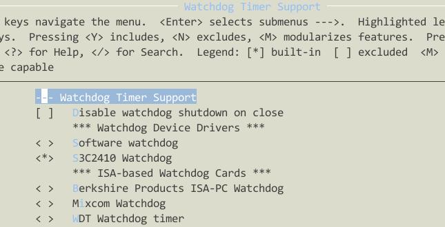
Watchdog configuraiton in kernel:
$ grep "CONFIG_S3C2410_WATCHDOG_DEFAULT_TIME" ./ -r
./drivers/watchdog/s3c2410_wdt.c:#define CONFIG_S3C2410_WATCHDOG_DEFAULT_TIME   (15)
Test Watchdog:
~ # dmesg | grep watchdog
s3c2410-wdt s3c2410-wdt: watchdog inactive, reset disabled, irq enabled
~ #
~ # echo 0>/dev/watchdog

s3c2410-wdt s3c2410-wdt: Unexpected close, not stopping watchdog
Then after 15 seconds your board will reset, disable watchdog via:
~ # echo -n V>/dev/watchdog
LED
The connection for LED is:
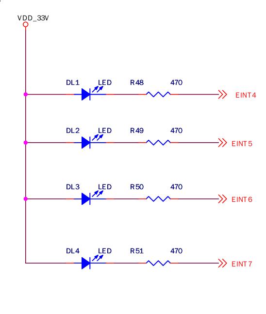
Saw s3c2440 chip connection:
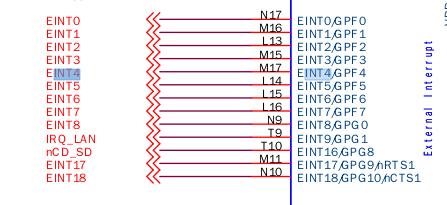
Connection in text:
EINT4 GPF4 DL1
EINT5 GPF5 DL2
EINT6 GPF6 DL3
EINT7 GPF7 DL4
Code changes:
#include <linux/miscdevice.h>
#include <linux/delay.h>
#include <asm/irq.h>
#include <mach/regs-gpio.h>
#include <mach/hardware.h>
#include <linux/kernel.h>
#include <linux/module.h>
#include <linux/init.h>
#include <linux/mm.h>
#include <linux/fs.h>
#include <linux/types.h>
#include <linux/delay.h>
#include <linux/moduleparam.h>
#include <linux/slab.h>
#include <linux/errno.h>
#include <linux/ioctl.h>
#include <linux/cdev.h>
#include <linux/string.h>
#include <linux/list.h>
#include <linux/pci.h>
#include <linux/gpio.h>
#include <asm/uaccess.h>
#include <asm/atomic.h>
#include <asm/unistd.h>
#define DEVICE_NAME "leds" //设备名(/dev/leds)
//LED 对应的GPIO 端口列表
static unsigned long led_table [] = {
 S3C2410_GPF(4),
 S3C2410_GPF(5),
 S3C2410_GPF(6),
 S3C2410_GPF(7),
};
//LED 对应端口将要输出的状态列表
static unsigned int led_cfg_table [] = {
 S3C2410_GPIO_OUTPUT,
 S3C2410_GPIO_OUTPUT,
 S3C2410_GPIO_OUTPUT,
 S3C2410_GPIO_OUTPUT,
};
/*ioctl 函数的实现
* 在应用/用户层将通过ioctl 函数向内核传递参数,以控制LED 的输出状态
*/
static int leds_ioctl(struct inode *inode,
          struct file *file,
          unsigned int cmd,
          unsigned long arg)
{
 switch(cmd) {
  case 0:
  case 1:
    if (arg > 4) {
     return -EINVAL;
    }
  //根据应用/用户层传递来的参数(取反),通过s3c2410_gpio_setpin 函数设置LED 对应的端口寄存器
  s3c2410_gpio_setpin(led_table[arg], !cmd);
   return 0;
  default:
    return -EINVAL;
 }
}
/*
* 设备函数操作集,在此只有ioctl 函数,通常还有read, write, open, close 等,因为本LED 驱动在下面已经
* 注册为misc 设备,因此也可以不用open/close
*/
static struct file_operations dev_fops = {
 .owner = THIS_MODULE,
 .ioctl = leds_ioctl,
};
/*
* 把LED 驱动注册为MISC 设备
*/
static struct miscdevice misc = {
 .minor = MISC_DYNAMIC_MINOR, //动态设备号
 .name = DEVICE_NAME,
 .fops = &dev_fops,
};
/*
* 设备初始化
*/
static int __init dev_init(void)
{
 int ret;
 int i;
 for (i = 0; i < 4; i++) {
  //设置LED 对应的端口寄存器为输出(OUTPUT)
  s3c2410_gpio_cfgpin(led_table[i], led_cfg_table[i]);
  //设置LED 对应的端口寄存器为低电平输出,在模块加载结束后,四个LED 应该是全部都是发光状态
  s3c2410_gpio_setpin(led_table[i], 0);
 }
 ret = misc_register(&misc); //注册设备

 if(ret < 0)
 {
        printk(DEVICE_NAME "register falid!\n");
        return ret;
  }

 printk (DEVICE_NAME "\tinitialized\n"); //打印初始化信息
 return 0;
}
static void __exit dev_exit(void)
{
 misc_deregister(&misc);
}
//模块初始化,仅当使用insmod/podprobe 命令加载时有用,如果设备不是通过模块方式加载,此处将不会被调用
module_init(dev_init);
//卸载模块,当该设备通过模块方式加载后,可以通过rmmod 命令卸载,将调用此函数
module_exit(dev_exit);
MODULE_LICENSE("GPL"); //版权信息
MODULE_AUTHOR("singleboy."); //开发者信息
Change Kconfig file:
config LEDS_SMDK2440
 tristate "LED Support for SMDK2440 GPIO LEDs"
 depends on SMDK2440_CPU2440
 default y if SMDK2440_CPU2440
 help
  This option enables support for LEDs connected to GPIO lines
  on SMDK2440 boards.
And the Makefile
obj-$(CONFIG_LEDS_SMDK2440) += smdk2440_leds.o
Rebuild the kernel and verify.
Test file:
#include <stdio.h>
#include <stdlib.h>
#include <unistd.h>
#include <sys/ioctl.h>

int main(int argc, char **argv)
{
 int on;
 int led_no;
 int fd;
 if (argc != 3 || sscanf(argv[1], "%d", &led_no) != 1 || sscanf(argv[2],"%d", &on) != 1 ||
     on < 0 || on > 1 || led_no < 0 || led_no > 3) {
  fprintf(stderr, "Usage: leds led_no 0|1\n");
  exit(1);
 }
 fd = open("/dev/leds0", 0);
 if (fd < 0) {
  fd = open("/dev/leds", 0);
 }
 if (fd < 0) {
  perror("open device leds");
  exit(1);
 }
 ioctl(fd, on, led_no);
 close(fd);
 return 0;
}
Then run test like:
/root # ./led 0 0
/root # ./led 1 0
/root # ./led 2 0
/root # ./led 2 1
/root # ./led 2 0
/root # ./led 3 0
Write a simple script
while true
 do
./led 0 0
sleep 1
./led 0 1
sleep 1
./led 1 0
sleep 1
./led 1 1
sleep 1
./led 2 0
sleep 1
./led 2 1
sleep 1
./led 3 0
sleep 1
./led 3 1
done
Now you could see led blinks.
Keys
First view the schematic to find the circle connection:
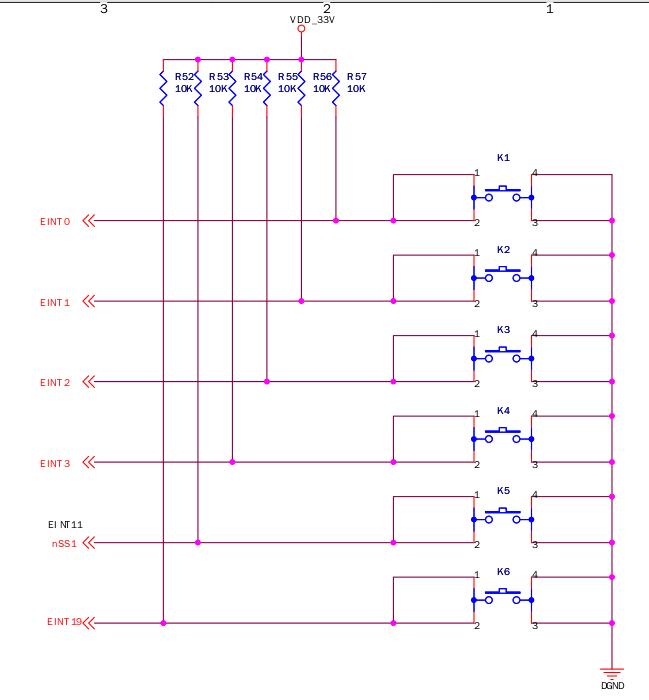
Keys connection:
K1	EINT0		GPF0
K2	EINT1		GPF1
K3	EINT2		GPF2
K4	EINT3		GPF3
K5	EINT11		GPG3
K6	EINT19		GPG11
The definition should be adjusted to the keys connection definition.
Edit the drivers/misc/smdk2440_buttons.c:
#include <linux/module.h>
#include <linux/kernel.h>
#include <linux/fs.h>
#include <linux/init.h>
#include <linux/delay.h>
#include <linux/poll.h>
#include <linux/irq.h>
#include <asm/irq.h>
#include <linux/interrupt.h>
#include <asm/uaccess.h>
#include <mach/regs-gpio.h>
#include <mach/hardware.h>
#include <linux/platform_device.h>
#include <linux/cdev.h>
#include <linux/miscdevice.h>
#include <linux/sched.h>
#include <linux/gpio.h>
#define DEVICE_NAME "buttons" //设备名称
/*定义中断所用的结构体*/
struct button_irq_desc {
 int irq; //按键对应的中断号
 int pin; //按键所对应的GPIO 端口
 int pin_setting; //按键对应的引脚描述,实际并未用到,保留
 int number; //定义键值,以传递给应用层/用户态
 char *name; //每个按键的名称
};
/*结构体实体定义*/
static struct button_irq_desc button_irqs [] = {
 {IRQ_EINT0, S3C2410_GPF(0), S3C2410_GPF0_EINT0, 0, "KEY0"},
 {IRQ_EINT1, S3C2410_GPF(1), S3C2410_GPF1_EINT1, 1, "KEY1"},
 {IRQ_EINT2, S3C2410_GPF(2), S3C2410_GPF2_EINT2, 2, "KEY2"},
 {IRQ_EINT3, S3C2410_GPF(3), S3C2410_GPF3_EINT3, 3, "KEY3"},
 {IRQ_EINT11, S3C2410_GPG(3), S3C2410_GPG3_EINT11, 4, "KEY4"},
 {IRQ_EINT19, S3C2410_GPG(11), S3C2410_GPG11_EINT19, 5, "KEY5"},
};
/*开发板上按键的状态变量,注意这里是’0’,对应的ASCII 码为30*/
static volatile char key_values [] = {'0', '0', '0', '0', '0', '0'};
/*因为本驱动是基于中断方式的,在此创建一个等待队列,以配合中断函数使用;当有按键按下并读取到键
值时,将会唤醒此队列,并设置中断标志,以便能通过 read 函数判断和读取键值传递到用户态;当没有按
键按下时,系统并不会轮询按键状态,以节省时钟资源*/
static DECLARE_WAIT_QUEUE_HEAD(button_waitq);
/*中断标识变量,配合上面的队列使用,中断服务程序会把它设置为1,read 函数会把它清零*/
static volatile int ev_press = 0;
/*本按键驱动的中断服务程序*/
static irqreturn_t buttons_interrupt(int irq, void *dev_id)
{
 struct button_irq_desc *button_irqs = (struct button_irq_desc *)dev_id;
 int down;
 // udelay(0);
 /*获取被按下的按键状态*/
 down = !s3c2410_gpio_getpin(button_irqs->pin);
 /*状态改变,按键被按下,从这句可以看出,当按键没有被按下的时候,寄存器的值为1(上拉),但按
  键被按下的时候,寄存器对应的值为0*/
 if (down != (key_values[button_irqs->number] & 1)) { // Changed
  /*如果key1 被按下,则key_value[0]就变为’1’,对应的ASCII 码为31*/
  key_values[button_irqs->number] = '0' + down;
  ev_press = 1; /*设置中断标志为1*/
  wake_up_interruptible(&button_waitq); /*唤醒等待队列*/
 }
 return IRQ_RETVAL(IRQ_HANDLED);
}
/*
*在应用程序执行open(“/dev/buttons”,…)时会调用到此函数,在这里,它的作用主要是注册6 个按键的中断。
*所用的中断类型是IRQ_TYPE_EDGE_BOTH,也就是双沿触发,在上升沿和下降沿均会产生中断,这样做
是为了更加有效地判断按键状态
*/
static int s3c24xx_buttons_open(struct inode *inode, struct file *file)
{
 int i;
 int err = 0;
 for (i = 0; i < sizeof(button_irqs)/sizeof(button_irqs[0]); i++) {
  if (button_irqs[i].irq < 0) {
   continue;
  }
  /*注册中断函数*/
  err = request_irq(button_irqs[i].irq, buttons_interrupt, IRQ_TYPE_EDGE_BOTH,
        button_irqs[i].name, (void *)&button_irqs[i]);
  if (err)
   break;
 }
 if (err) { /*如果出错,释放已经注册的中断,并返回*/
  i--;
  for (; i >= 0; i--) {
   if (button_irqs[i].irq < 0) {
    continue;
   }
   disable_irq(button_irqs[i].irq);
   free_irq(button_irqs[i].irq, (void *)&button_irqs[i]);
  }
  return -EBUSY;
 }
 /*注册成功,则中断队列标记为1,表示可以通过read 读取*/
 ev_press = 1;
 /*正常返回*/
 return 0;
}
/*
*此函数对应应用程序的系统调用close(fd)函数,在此,它的主要作用是当关闭设备时释放6 个按键的中断*
处理函数
*/
static int s3c24xx_buttons_close(struct inode *inode, struct file *file)
{
 int i;
 for (i = 0; i < sizeof(button_irqs)/sizeof(button_irqs[0]); i++) {
  if (button_irqs[i].irq < 0) {
   continue;
  }
  /*释放中断号,并注销中断处理函数*/
  free_irq(button_irqs[i].irq, (void *)&button_irqs[i]);
 }
 return 0;
}
/*
*对应应用程序的read(fd,…)函数,主要用来向用户空间传递键值
*/
static int s3c24xx_buttons_read(struct file *filp, char __user *buff, size_t count, loff_t *offp)
{
 unsigned long err;
 if (!ev_press) {
  if (filp->f_flags & O_NONBLOCK)
   /*当中断标识为0 时,并且该设备是以非阻塞方式打开时,返回*/
   return -EAGAIN;
  else
   /*当中断标识为0 时,并且该设备是以阻塞方式打开时,进入休眠状态,等待被唤醒*/
   wait_event_interruptible(button_waitq, ev_press);
 }
 /*把中断标识清零*/
 ev_press = 0;
 /*一组键值被传递到用户空间*/
 err = copy_to_user(buff, (const void *)key_values, min(sizeof(key_values), count));
 return err ? -EFAULT : min(sizeof(key_values), count);
}
static unsigned int s3c24xx_buttons_poll( struct file *file, struct poll_table_struct *wait)
{
 unsigned int mask = 0;
 /*把调用poll 或者select 的进程挂入队列,以便被驱动程序唤醒*/
 poll_wait(file, &button_waitq, wait);
 if (ev_press)
  mask |= POLLIN | POLLRDNORM;
 return mask;
}
/*设备操作集*/
static struct file_operations dev_fops = {
 .owner = THIS_MODULE,
 .open = s3c24xx_buttons_open,
 .release = s3c24xx_buttons_close,
 .read = s3c24xx_buttons_read,
 .poll = s3c24xx_buttons_poll,
};
static struct miscdevice misc = {
 .minor = MISC_DYNAMIC_MINOR,
 .name = DEVICE_NAME,
 .fops = &dev_fops,
};
/*设备初始化,主要是注册设备*/
static int __init dev_init(void)
{
 int ret;
 /*把按键设备注册为misc 设备,其设备号是自动分配的*/
 ret = misc_register(&misc);

 if(ret < 0)
  {
        printk(DEVICE_NAME "register falid!\n");
        return ret;
   }
 printk (DEVICE_NAME"\tinitialized\n");
 return 0;
}
/*注销设备*/
static void __exit dev_exit(void)
{
 misc_deregister(&misc);
}
module_init(dev_init); //模块初始化,仅当使用insmod/podprobe 命令加载时有用,如果设备不是通过模块方式加载,此处将不会被调用
module_exit(dev_exit); //卸载模块,当该设备通过模块方式加载后,可以通过rmmod 命令卸载,将调用此函数
MODULE_LICENSE("GPL"); //版权信息
MODULE_AUTHOR("singleboy."); //作者名字
Edit the Kconfig file:
 config SMDK2440_BUTTONS
  tristate "Buttons driver for SMDK2440 development boards"
  depends on SMDK2440_CPU2440
  default y if SMDK2440_CPU2440
  help
   this is buttons driver for SMDK2440 development boards
Also change the Makefile:
obj-$(CONFIG_SMDK2440_BUTTONS) += smdk2440_buttons.o
Make the kernel out and verify it on board.
Test code:
#include <stdio.h>
#include <stdlib.h>
#include <unistd.h>
#include <sys/ioctl.h>
#include <sys/types.h>
#include <sys/stat.h>
#include <fcntl.h>
#include <sys/select.h>
#include <sys/time.h>
#include <errno.h>

int main(void)
{
 int buttons_fd;
 char buttons[6] = {'0', '0', '0', '0', '0', '0'}; //定义按键值变量,对于驱动函数中的key_values 数组

 buttons_fd = open("/dev/buttons", 0); /*打开按键设备/dev/buttons*/
 if (buttons_fd < 0) {
  perror("open device buttons"); /*打开失败则退出*/
  exit(1);
 }

 for (;;) { /*永读按键并打印键值和状态*/
  char current_buttons[6];
  int count_of_changed_key;
  int i;

/*使用read 函数读取一组按键值(6 个)*/
  if (read(buttons_fd, current_buttons, sizeof current_buttons) != sizeof current_buttons) {
   perror("read buttons:");
   exit(1);
  }

/*逐个分析读取到的按键值*/

  for (i = 0, count_of_changed_key = 0; i < sizeof buttons / sizeof buttons[0]; i++) {
   if (buttons[i] != current_buttons[i]) {
    buttons[i] = current_buttons[i];

/*打印按键值,并标明按键按下/抬起的状态*/
    printf("%skey %d is %s", count_of_changed_key? ", ": "", i+1, buttons[i] == '0' ? "up" : "down");
    count_of_changed_key++;
   }
  }
  if (count_of_changed_key) {
   printf("\n");
  }
 }

 close(buttons_fd); /*关闭按键设备文件*/
 return 0;
}
Test Result:
/root # ./buttons
key 1 is down
key 1 is up
key 2 is down
key 2 is up
key 3 is down
key 3 is up
key 4 is down
Oct 27, 2014
TechnologyFlash Disk
Enable the scsi device support in kernel configuration:
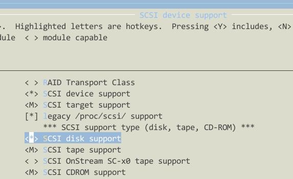
Then enable the usb support:
* Support for Host-side USB
* USB device filesystem(DEPRECATED)
* OHCI HCD support
* USB Mass Storage support
Also enable the filesystem support for FAT/FAT16/FAT32/EXT4:
change the default u-boot parameters:
utu-bootloader=>>>printenv bootcmd
bootcmd=nand read.i 0x32000000 0x60000 0x200000; bootm
utu-bootloader=>>>setenv bootcmd 'tftp 30000000 uImage; bootm'
utu-bootloader=>>>printenv bootcmd
bootcmd=tftp 30000000 uImage; bootm
utu-bootloader=>>>saveenv
Saving Environment to NAND...
Erasing Nand...Writing to Nand... done
Next time the reboot will directly download the kernel file from tftp server and bootm it from memory.
Also please enable the filesystem support on FAT/FAT32/ext4, etc, then next time you insert the USB Disk, it will automatically scanned and recognize your partitions.
MMC/SD
From the schematic image we could see:
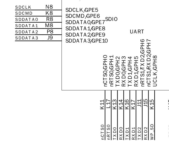
Add the following definition in arch/arm/mach-s3c2440/mach-smdk2440.c:
// Added for mmc
#include <linux/mmc/host.h>
#include <plat/mci.h>

/* MMC/SD */
static struct s3c24xx_mci_pdata smdk2440_mmc_cfg = {
    .gpio_detect = S3C2410_GPG(8),
    .gpio_wprotect = S3C2410_GPH(8),
    .set_power = NULL,
    .ocr_avail = MMC_VDD_32_33|MMC_VDD_33_34,
};

static struct platform_device *smdk2440_devices[] __initdata = {
	//........
	&s3c_device_sdi,  // Added SD card into the platform equipments
};

static void __init smdk2440_machine_init(void)
{

+    	/* Add support for mmc in smdk2440 */
+	s3c_device_sdi.dev.platform_data = &smdk2440_mmc_cfg;
Kernel configuration:
Device Drivers --->
<*> MMC/SD/SDIO card support --->
<*> MMC block device driver
<*> Secure Digital Host Controller Interface support
<*> Samsung S3C SD/MMC Card Interface support
Then re-compile the kernel and verify.
Only 1G’s mmc card could be supported currently. I didn’t test other volumns.
Sound Card
The sound card’s schematic is listed as:
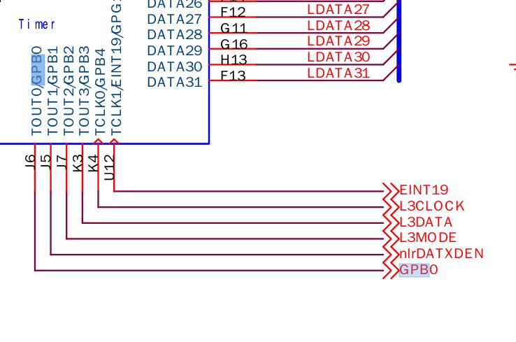
Then made code changes in:
// Sound Card
#include <sound/s3c24xx_uda134x.h>


/*Sound card*/
static struct s3c24xx_uda134x_platform_data s3c24xx_uda134x_data = {
    .l3_clk = S3C2410_GPB(4),
    .l3_data = S3C2410_GPB(3),
    .l3_mode = S3C2410_GPB(2),
    .model = UDA134X_UDA1341,
};


static struct platform_device s3c24xx_uda134x = {
    .name = "s3c24xx_uda134x",
         .dev = {
         .platform_data = &s3c24xx_uda134x_data,
    }
};

static struct platform_device *smdk2440_devices[] __initdata = {
	//.........
        &s3c24xx_uda134x, // Register the UDA1341 platform device to kernel
};
Kernel Configuration:
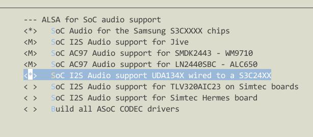
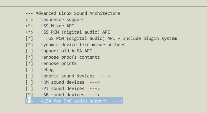
Then re-compile the kernel and verify it on utu2440.
Test steps:
$ cat /root/test.wav>/dev/dsp
$ cat /proc/devices
10 misc
 13 input
 14 sound
 21 sg
 29 fb
Now cross-compile mad-player for playing mp3.
Download the madplayer and cross-compiler.
$ ./configure CC=arm-linux-gcc --host=arm --prefix=/srv/nfs4/rootfs/usr/
$ make clean && make
$ sudo make install
Trouble shooting:
/bin # /bin/sh madplay
madplay: line 1: syntax error: unexpected word (expecting ")")

[Trusty@/media/y/embedded/utu2440/App/madplay-0.15.2b]$ arm-linux-readelf -a madplay | grep interpreter
      [Requesting program interpreter: /lib/ld-linux.so.3]
Solution: copy all of the dynamic library from the cross-compiler to the root file system:
$ sudo cp -f /opt/cross/arm-linux-gcc_4.3.2/arm-none-linux-gnueabi/libc/armv4t/lib/*so* /srv/nfs4/rootfs/lib -a
Download the libmad from:
http://sourceforge.net/projects/mad/files/libmad/0.15.1b/libmad-0.15.1b.tar.gz/download
$ ./configure --prefix=/srv/nfs4/rootfs/usr/ --host=arm-linux CC=arm-linux-gcc
$ make && make install
When run madplay, it will complains the Bus Error, need further debugging.
Oct 27, 2014
TechnologyMainly recorded the steps for installation:
# apt-get install python-pip
# pip install shadowsocks
# vim /etc/shadowsocks.json
{
    "server":"1xx.xxx.xxx.xxx",
    "server_port":xxxx,
    "local_address": "127.0.0.1",
    "local_port":1080,
    "password":"Pass!Pass!Pass",
    "timeout":300,
    "method":"aes-256-cfb",
    "fast_open": false,
    "workers": 1
}
# apt-get install supervisor
# vim /etc/supervisor/conf.d/shadowsocks.conf
[program:shadowsocks]
command=ssserver -c /etc/shadowsocks.json
autorestart=true
user=nobody
# vim /etc/default/supervisor
ulimit -n 51200
# service supervisor start
Then in client you could use a shadownsocks client for connecting to remote servers and enjoy the free internet.