Nov 18, 2014
TechnologyFirst get the installation image from the AppStore, then format a flash-disk more than 8G to following format:
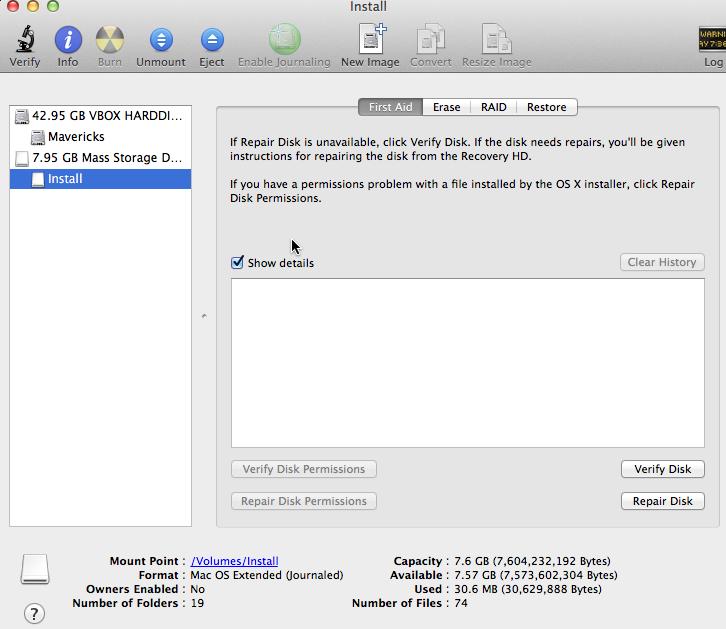
Use following commands for creating the installation media:
kkkkkkkktttt-iMac:~ Trusty$ sudo /Applications/Install\ OS\ X\ Yosemite.app/Contents/Resources/createinstallmedia --volume /Volumes/Install --applicationpath /Applications/Install\ OS\ X\ Yosemite.app --nointeraction
Take a coffee, cause this will spend a long time for copying everything you need into the disk.
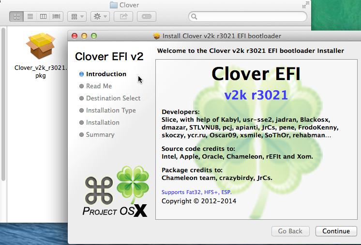
Install Clover:
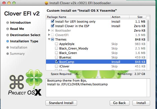
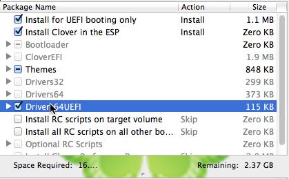
Customize Clover installation:
Copy the dsdt & ssdt files to EFI partition:
kkkkkkkktttt-iMac:Dsdt & Ssdt Trusty$ pwd
/Users/Trusty/Desktop/MacOS/SurfacePro/SurfacePro 1° Gen FilesPackage V.0.5.1/Dsdt & Ssdt
kkkkkkkktttt-iMac:Dsdt & Ssdt Trusty$ cp -ar * /Volumes/ESP/EFI/CLOVER/ACPI/patched/
Copy some device driver files into the Clover:
kkkkkkkktttt-iMac:MacOS Trusty$ tar xzvf GenericUSBXHCI_1.2.7.tar.gz
Copy GenericUSBXHCI.kext to 10.9/ 10.10/ Other/:
kkkkkkkktttt-iMac:kexts Trusty$ pwd
/Volumes/ESP/EFI/CLOVER/kexts
kkkkkkkktttt-iMac:kexts Trusty$ ls -F
10.10/  10.6/   10.7/   10.8/   10.9/   Other/
kkkkkkkktttt-iMac:10.10 Trusty$ sudo cp -r  /Users/Trusty/Desktop/MacOS/GenericUSBXHCI_Yosemite/ /Volumes/ESP/EFI/CLOVER/kexts/10.10/
Also we have to copy the fakesmc.kext should be copied to above folder.
kkkkkkkktttt-iMac:kexts Trusty$ ls *
10.10:
GenericUSBXHCI.kext     fakesmc.kext

10.6:

10.7:

10.8:

10.9:
GenericUSBXHCI.kext     fakesmc.kext

Other:
GenericUSBXHCI.kext     fakesmc.kext
Now copy the config.plist into the CLOVER root directory.
kkkkkkkktttt-iMac:SurfacePro 1° Gen FilesPackage V.0.5.1 Trusty$ pwd
/Users/Trusty/Desktop/MacOS/SurfacePro/SurfacePro 1° Gen FilesPackage V.0.5.1
kkkkkkkktttt-iMac:SurfacePro 1° Gen FilesPackage V.0.5.1 Trusty$ ls config.plist
config.plist
Now you got your installation disk OK.
Nov 17, 2014
TechnologySince the 5901 port is forbiddended via administrator of the switch, we have to forward the traffic to remote machine via ssh:
First in our machine type following command:
ssh -L 2333:A:5901 A -l Trusty
This will forward the A machines’ 5901 to local’s 2333 port.
Then use a vncviewer software for accessing local machine’s 2333 port:
vncviewer localhost:2333
Notice, the virtualbox’s is named to vboxgtk in opensuse.
Nov 16, 2014
TechnologyPWM
Simply enable the P9_21 to PWM, then connect to the LED. The LED connection could refer to EBC Exercises on BBB - Control LED
SLOTS=/sys/devices/bone_capemgr.*/slots
echo am33xx_pwm > $SLOTS
echo bone_pwm_P9_21 > $SLOTS
cd /sys/devices/ocp.3/pwm_test_P9_21.15/
echo 1000000000 > period
echo  250000000 > duty
echo 1 > run
From now you could see the LED begin to flash. In fact using this pwm we could control servo motor:
http://www.linux.com/learn/tutorials/776799-servo-control-from-the-beaglebone-black/
Nov 16, 2014
TechnologyOperate On Device Tree
Turn off the trigger and then shine on the LED USR3 via following command:
root@arm:~# cd /sys/class/leds/beaglebone\:green\:usr3
root@arm:/sys/class/leds/beaglebone:green:usr3# ls
brightness  device  max_brightness  power  subsystem  trigger  uevent
root@arm:/sys/class/leds/beaglebone:green:usr3# echo none > trigger
root@arm:/sys/class/leds/beaglebone:green:usr3# echo 1 > brightness
We could find the gpio is attached to which pin:
# ./findGPIO.js USR3
{ name: 'USR3',
 gpio: 56,
 led: 'usr3',
 mux: 'gpmc_a8',
 key: 'USR3',
 muxRegOffset: '0x060',
 options:
  [ 'gpmc_a8',
    'gmii2_rxd3',
    'rgmii2_rd3',
    'mmc2_dat6',
    'gpmc_a24',
    'pr1_mii1_rxd0',
    'mcasp0_aclkx',
    'gpio1_24' ] }
USR3 (gpio 56) mode: 7 (gpio1_24) 0x060 pullup
pin 24 (44e10860): (MUX UNCLAIMED) (GPIO UNCLAIMED)
gpio1_24 is what we want. Then refer Memory Map table in the Technical Reference Manual, its base address is 0x4804c000.
devmem2
An easy way to read the contents of a memory location is with devmem2:
root@arm:~/code/gpio# devmem2 0x4804c13c
/dev/mem opened.
Memory mapped at address 0xb6fea000.
Value at address 0x4804C13C (0xb6fea13c): 0x9A00000
Light ON the USR3 led:
root@arm:~/code/gpio# devmem2 0x4804c190 w 0x01000000
/dev/mem opened.
Memory mapped at address 0xb6f52000.
Value at address 0x4804C190 (0xb6f52190): 0x9800000
Written 0x1000000; readback 0x1000000
Light OFF the USR3 led:
root@arm:~/code/gpio# devmem2 0x4804c194 w 0x01000000
/dev/mem opened.
Memory mapped at address 0xb6f1c000.
Value at address 0x4804C194 (0xb6f1c194): 0x8A00000
Written 0x1000000; readback 0x1000000
mmap code
The critical Code:
    int fd = open("/dev/mem", O_RDWR);

    gpio_addr = mmap(0, GPIO1_SIZE, PROT_READ | PROT_WRITE, MAP_SHARED, fd, GPIO1_START_ADDR);

    gpio_oe_addr           = gpio_addr + GPIO_OE;
    gpio_setdataout_addr   = gpio_addr + GPIO_SETDATAOUT;
    gpio_cleardataout_addr = gpio_addr + GPIO_CLEARDATAOUT;

    // Set USR3 to be an output pin
    reg = *gpio_oe_addr;
    printf("GPIO1 configuration: %X\n", reg);
    reg &= ~USR3;       // Set USR3 bit to 0
    *gpio_oe_addr = reg;
    printf("GPIO1 configuration: %X\n", reg);

    printf("Start blinking LED USR3\n");
    while(keepgoing) {
        // printf("ON\n");
        *gpio_setdataout_addr = USR3;
        usleep(250000);
        // printf("OFF\n");
        *gpio_cleardataout_addr = USR3;
        usleep(250000);
    }
Run the program and see its heartbeat:
# ./gpioToggle
Mapping 4804C000 - 4804E000 (size: 2000)
GPIO mapped to 0xb6f91000
GPIO OE mapped to 0xb6f91134
GPIO SETDATAOUTADDR mapped to 0xb6f91194
GPIO CLEARDATAOUT mapped to 0xb6f91190
GPIO1 configuration: F60FFFFF
GPIO1 configuration: F60FFFFF
Start blinking LED USR3
gpioThru
This example need to be clearly written later.
Nov 16, 2014
TechnologyConnection
HMC5883L magnetometer runs in 400KHZ I2C bus, it’s for measuring the magnetic field vector in 3 dimensions.
We use its 4 ports: VCC,GND,SDA, SCL. SDA is for Data, while SCL is for Clock.
Use P9 for connecting the HMC5883L.
P9_02(GND) <----> GND
P9_04(VCC) <----> VCC
P9_19(I2C2_SCL) <----> SCL	 I2C bus 2(pin 19 on header p9 to SCL)
P9_20(I2C2_SDA) <----> SDA
I2C Detect
First you should install i2cdetect, then list the avaiable i2c bus via following command:
root@arm:~# i2cdetect -l
i2c-0   i2c             OMAP I2C adapter                        I2C adapter
i2c-1   i2c             OMAP I2C adapter                        I2C adapter
We choose i2c bus2, thus the command for detecting the connected device should be:
root@arm:~# i2cdetect -y -r 1
     0  1  2  3  4  5  6  7  8  9  a  b  c  d  e  f
00:          -- -- -- -- -- -- -- -- -- -- -- -- --
10: -- -- -- -- -- -- -- -- -- -- -- -- -- -- 1e --
20: -- -- -- -- -- -- -- -- -- -- -- -- -- -- -- --
30: -- -- -- -- -- -- -- -- -- -- -- -- -- -- -- --
40: -- -- -- -- -- -- -- -- -- -- -- -- -- -- -- --
50: -- -- -- -- UU UU UU UU -- -- -- -- -- -- -- --
60: -- -- -- -- -- -- -- -- -- -- -- -- -- -- -- --
70: -- -- -- -- -- -- -- --
The address should be 0x1e.
Communicate with HMC5883L
The registers are listed as following, notice eavh value for each axis are 16-bits, thus we have to read them seperately and combine them:
Address	Name	Access
00	Configuration Register A	Read/Write
01	Configuration Register B	Read/Write
02	Mode Register	Read/Write
03	Data Output X MSB Register	Read
04	Data Output X LSB Register	Read
05	Data Output Z MSB Register	Read
06	Data Output Z LSB Register	Read
07	Data Output Y MSB Register	Read
08	Data Output Y LSB Register	Read
09	Status Register	Read
10	Identification register A	Read
11	Identification register B	Read
12	Identification register C	Read
Thus we could read out the X MSB Restier and X LSB Register via:
root@arm:~# i2cget -y 1 0x1e 3
0xfe
root@arm:~# i2cget -y 1 0x1e 4
0x91
Different Mode
Notice Mode Register, this will set the mesurement mode.
From the above table, we know for setting the lower 2 bits we could enable the operation mode of HMC5883L.
Now we set to single measurement mode, for one-time measure.
# i2cset -y 1 0x1e 2 1
2 means we set the register 2, and its number equals to 01(Single-Measurement Mode). After one-time measurement, it wil fall back to idle Mode.
After one-time measurement, get the register mode:
root@arm:~# i2cget -y 1 0x1e 2
0x03
Get the value of x-axis:
root@arm:~# i2cget -y 1 0x1e 3
0xfe
root@arm:~# i2cget -y 1 0x1e 4
0x77
C Code
Running Result:
root@arm:~/code/i2c# ./myi2cget 1 30 2
0x03 (3)
root@arm:~/code/i2c# ./myi2cget 1 30 34
0x00 (0)
root@arm:~/code/i2c# ./myi2cget 1 30 4
0x77 (119)
Critical Code:
Open the i2c-xxx:
        sprintf(filename, "/dev/i2c-%d", i2cbus);
        file = open(filename, O_RDWR);
ioctl for setting the address:
if (ioctl(file, I2C_SLAVE, address) < 0) {
Now read the byte from:
res = i2c_smbus_read_byte_data(file, daddress);
Comparing the official i2cget, myi2cget could print out the human-readable format of data.
Web Displaying
Git clone the following project form github.com:
# git clone https://github.com/duganje/ECE497_duganje.git
# cd  ECE497_duganje/
# ls
MiniProject01  MiniProject02  MiniProject03  MiniProject04  README.md
Upload the project MiniProject04 to the BBB board.
Notice change the code in buttonBox.js from i2cset -y 3 to i2cset -y 1 and i2cget -y 3toi2cget -y 1`
After modification, run buttonBox.js via:
$ node buttonBox.js
Now visit the http://xx.xx.xx.xxx:8081/buttonBox.html you could see the data displayed as following: