Feb 29, 2016
Technology连线/电路
不需要对电路做任何修改,仅替换arduino里的程序即可。
代码
代码如下:
hid_custom_rq/
hid_data/
hid_mouse/
编译方法和上面一样。
值得注意的是, 这三个设备都是实现了HID设备,可以做到即插即用。
hid_data的用法:
读取/写入例子:
➜  commandline ./hidtool read
0x01 0x02 0x03 0x04 0x05 0x06 0x00 0x00 0x00 0x00 0x00 0x00 0x00 0x00 0x00 0x00
0x00 0x00 0x00 0x00 0x00 0x00 0x00 0x00 0x00 0x00 0x00 0x00 0x00 0x00 0x00 0x00
0x00 0x00 0x00 0x00 0x00 0x00 0x00 0x00 0x00 0x00 0x00 0x00 0x00 0x00 0x00 0x00
0x00 0x00 0x00 0x00 0x00 0x00 0x00 0x00 0x00 0x00 0x00 0x00 0x00 0x00 0x00 0x00
0x00 0x00 0x00 0x00 0x00 0x00 0x00 0x00 0x00 0x00 0x00 0x00 0x00 0x00 0x00 0x00
0x00 0x00 0x00 0x00 0x00 0x00 0x00 0x00 0x00 0x00 0x00 0x00 0x00 0x00 0x00 0x00
0x00 0x00 0x00 0x00 0x00 0x00 0x00 0x00 0x00 0x00 0x00 0x00 0x00 0x00 0x00 0x00
0x00 0x00 0x00 0x00 0x00 0x00 0x00 0x00 0x00 0x00 0x00 0x00 0x00 0x00 0x00 0x00
➜  commandline ./hidtool write 0x34 0x54 0x20 0x1f
➜  commandline ./hidtool read
0x34 0x54 0x20 0x1f 0x00 0x00 0x00 0x00 0x00 0x00 0x00 0x00 0x00 0x00 0x00 0x00
0x00 0x00 0x00 0x00 0x00 0x00 0x00 0x00 0x00 0x00 0x00 0x00 0x00 0x00 0x00 0x00
0x00 0x00 0x00 0x00 0x00 0x00 0x00 0x00 0x00 0x00 0x00 0x00 0x00 0x00 0x00 0x00
0x00 0x00 0x00 0x00 0x00 0x00 0x00 0x00 0x00 0x00 0x00 0x00 0x00 0x00 0x00 0x00
0x00 0x00 0x00 0x00 0x00 0x00 0x00 0x00 0x00 0x00 0x00 0x00 0x00 0x00 0x00 0x00
0x00 0x00 0x00 0x00 0x00 0x00 0x00 0x00 0x00 0x00 0x00 0x00 0x00 0x00 0x00 0x00
0x00 0x00 0x00 0x00 0x00 0x00 0x00 0x00 0x00 0x00 0x00 0x00 0x00 0x00 0x00 0x00
0x00 0x00 0x00 0x00 0x00 0x00 0x00 0x00 0x00 0x00 0x00 0x00 0x00 0x00 0x00 0x00
custom_class延伸
连线LED 11,修改代码后即可控制11 GPIO口的LED亮灭
custom_class_demo.pde:
const int ledPin = 11;
custom_class.h:
class custom_classDevice {
 public:
  custom_classDevice() {
    usbInit();
    ledPin = 11;        // pin 11 as default ledPin
  }
而后连接一个220欧电阻+LED到ARDUINO的PIN 11上,即可通过USB控制LED亮灭。
Feb 26, 2016
Technology参考
参考链接如下(需翻墙):
V-USB examples for Arduino
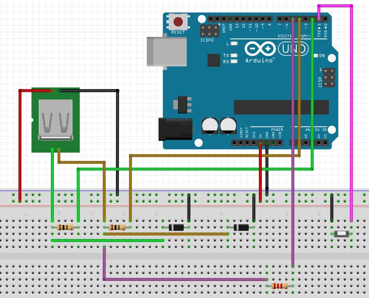
连线图
链接里的连线图如下:
这个图我想了很久,对比上一节里键盘的连线图对比,发现D+/D-的连线刚好是反过来的。此外就是
D-上加了一个上拉电阻, 电阻值为1.5K, 这个其实没关系,在我们的例子中,用到2.2K,是因为
我们用的参考电压是5V的。
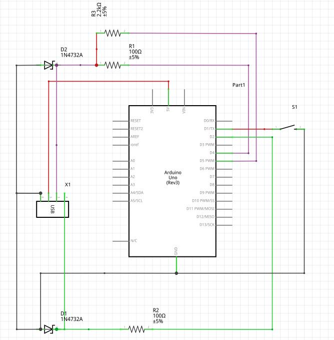
对上一章我们的连线图进行修改,得出的连线图如下:
电路图如下:
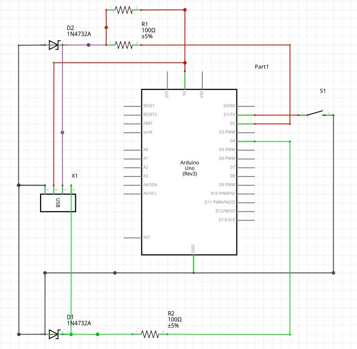
上一章用到的开关可以不用拆除。
值得注意的是,2.2K的上拉电阻接到了5V输入。
代码
下载Windows版0022 Arduino,编译原帖中pde文件并上传,修改
hardware/arduino/cores/arduino/wiring.c里的:
SIGNAL(TIMER0_OVF_vect)
{
++++++   sei()
......
}
客户端程序编译:
➜  pwd
......../custom_class/examples/custom_class_demo/commandline
➜  make clean
rm -f *.o set-led
➜  make
使用./set-led即可,编译前需要修改头文件:
$ vim set-led.c
//#include "../firmware/requests.h"   /* custom request numbers */
//#include "../firmware/usbconfig.h"  /* device's VID/PID and names */
#include "../../../requests.h"   /* custom request numbers */
#include "../../../usbconfig.h"  /* device's VID/PID and names */
Feb 26, 2016
Technology参考
主要参考了:
Arduino学习笔记A11 - Arduino模拟电脑键盘(基于AVR-USB的USB-HID设备)
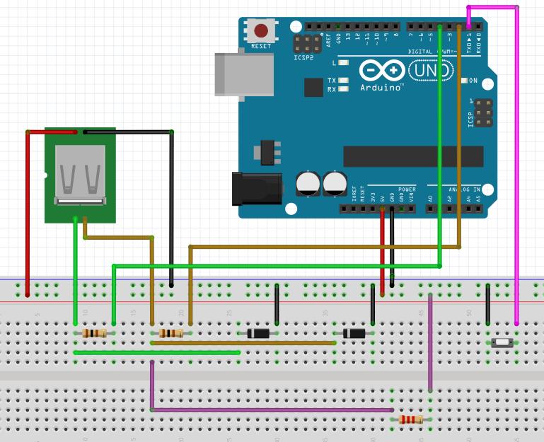
电路图
安装Fritzing后,可以绘制出面包板连线图和电路图:
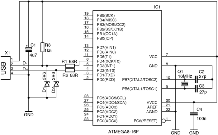
电路图:
注意事项:
电阻换成100欧也可以,原帖中是68欧电阻。
注意齐纳二极管的极性,带有色条的一端是负极。
代码
值得注意的配置如下:
#define USB_CFG_IOPORTNAME D

USB输入输出引脚使用AVR单片机的PORTD,如果改成B就是使用PORTB
#define USB_CFG_DMINUS_BIT 4

USB的D-接PORTD的第四位PD4,对应Arduino D4
#define USB_CFG_DPLUS_BIT  2

USB的D+接PORTD的第二位PD2,对应Arduino D2
#define USB_CFG_PULLUP_IOPORTNAME D

USB上拉引脚使用AVR单片机的PORTD,如果改成B就是使用PORTB
#define USB_CFG_PULLUP_BIT  5

USB的上拉电阻接PORTD的第五位PD5,对应Arduino  D5
在Arduino1.0.5上编译/配置都没有问题,最好在0022~1.05的版本范围内进行实验。
首先通过USBasp线写入编译后的程序,而后换上我们添加的USB线缆后,点击按键,每次即可输出
hello world字符串。
Feb 25, 2016
TechnologyBefore
Add 2 NICs, and show their ip infos via:
[root@localhost ~]# ifconfig
eth0: flags=4163<UP,BROADCAST,RUNNING,MULTICAST>  mtu 1500
        inet 10.47.58.207  netmask 255.255.255.0  broadcast 10.47.58.255
        inet6 fe80::5054:ff:feae:f2be  prefixlen 64  scopeid 0x20<link>
        ether 52:54:00:ae:f2:be  txqueuelen 1000  (Ethernet)
        RX packets 75  bytes 10924 (10.6 KiB)
        RX errors 0  dropped 5  overruns 0  frame 0
        TX packets 15  bytes 1668 (1.6 KiB)
        TX errors 0  dropped 0 overruns 0  carrier 0  collisions 0

eth1: flags=4163<UP,BROADCAST,RUNNING,MULTICAST>  mtu 1500
        inet 10.47.58.135  netmask 255.255.255.0  broadcast 10.47.58.255
        inet6 fe80::5054:ff:fe56:8c2e  prefixlen 64  scopeid 0x20<link>
        ether 52:54:00:56:8c:2e  txqueuelen 1000  (Ethernet)
        RX packets 108  bytes 17136 (16.7 KiB)
        RX errors 0  dropped 5  overruns 0  frame 0
        TX packets 47  bytes 6928 (6.7 KiB)
        TX errors 0  dropped 0 overruns 0  carrier 0  collisions 0
Install Openvswitch
Install/Configure ovs via:
# yum localinstall /home/ovs/rpmbuild/RPMS/x86_64/openvswitch-2.3.2-1.x86_64.rpm
# systemctl start openvswitch.service
# chkconfig openvswitch on
# ovs-vsctl -V
ovs-vsctl (Open vSwitch) 2.3.2
Compiled Feb 23 2016 10:12:37
DB Schema 7.6.2
Add bridge and list the added bridge:
[root@localhost ~]# ovs-vsctl add-br br0
[root@localhost ~]# ovs-vsctl list-br
br0
[root@localhost ~]# ovs-vsctl show
fb542c8e-968a-4dcf-b55f-934667abc7d3
    Bridge "br0"
        Port "br0"
            Interface "br0"
                type: internal
    ovs_version: "2.3.2"
Add bonding:
# ovs-vsctl add-bond br0 bond0 eth0 eth1
Or? ??
$ ovs-vsctl add-bond br0 bond0 eth1 eth0 bond_mode=balance-slb other_config:lacp-time=fast
Configure eth0/eth1/br0:
[root@localhost network-scripts]# cat /etc/sysconfig/network-scripts/ifcfg-eth0
# Generated by dracut initrd
DEVICE="eth0"
ONBOOT=yes
NETBOOT=yes
UUID="8dbd22bd-764d-48d0-b896-99ae358aebcc"
IPV6INIT=yes
BOOTPROTO="none"
TYPE=Ethernet
NAME="eth0"
[root@localhost network-scripts]# cat /etc/sysconfig/network-scripts/ifcfg-eth1
# Generated by dracut initrd
DEVICE="eth1"
ONBOOT=yes
NETBOOT=yes
IPV6INIT=yes
BOOTPROTO="none"
TYPE=Ethernet
NAME="eth1"
[root@localhost network-scripts]# cat /etc/sysconfig/network-scripts/ifcfg-br0
# Generated by dracut initrd
DEVICE="br0"
ONBOOT=yes
DEVICETYPE="ovs"
NETBOOT=yes
IPV6INIT=yes
BOOTPROTO=dhcp
TYPE="OVSBridge"
NAME="br0"
now restart the machine, you will get ovs bonding networking working.
Feb 23, 2016
TechnologyJust paste some python scripts:
>>> import imaplib
>>> obj=imaplib.IMAP4_SSL('imap.163.com','993')
>>> obj.login('XXXXX','XXXXXXXX')
('OK', [b'LOGIN completed'])
>>> obj.select()
('OK', [b'49'])
>>> obj.search(None,'Unseen')
('OK', [b''])
>>> len(obj.search(None, 'UnSeen')[1][0].split())
0
>>> len(obj.search(None, 'UnSeen')[1][0].split())
1
>>> len(obj.search(None, 'UnSeen')[1][0].split())
2
>>> len(obj.search(None, 'UnSeen')[1][0].split())
2
>>> len(obj.search(None, 'UnSeen')[1][0].split())
1
>>>
Using the unread counts, you could easily interact with some other programs,
for example shining LEDs.