Tips On NodeMCU
Mar 27, 2016
Technology
电路图
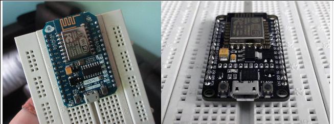
在淘宝上买的NodeMCU是v1.0版的, v0.9版和v1.0版的差别如下:
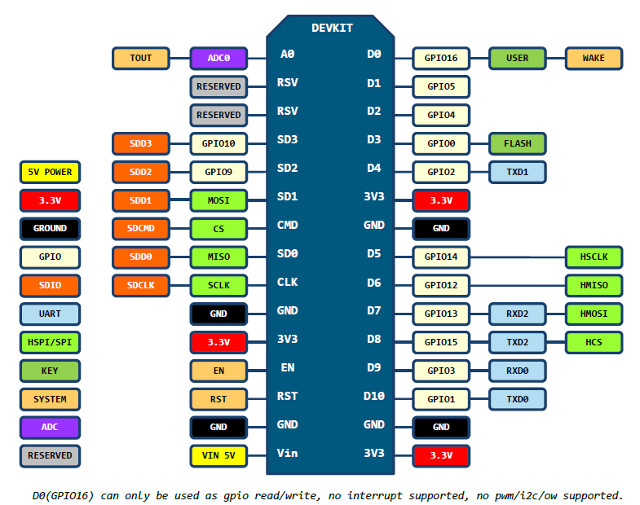
1.0版的连线如图:
烧写固件
ArchLinux下,可以通过python程序直接烧写固件.
下载integer版本的固件,
$ wget https://github.com/nodemcu/nodemcu-firmware/releases/download/0.9.6-dev_20150704/nodemcu_integer_0.9.6-dev_20150704.bin
下载esp-tool, ArchLinux需要安装python2版本的pyserial库才能运行该软件:
$ git clone https://github.com/themadinventor/esptool.git
$ sudo pacman -S python2-pyserial
$ sudo python2 ./esptool.py --port /dev/ttyUSB0 --write_flash 0x0000 ../nodemcu_integer_0.9.6-dev_20150704.bin
Minicom串口
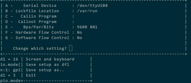
Minicom串口配置如下:
烧写完固件后,最简单的测试如下:
> print "Hello World"
Hello World
同时我们可以看下NodeMCU的版本,命令如下:
> majorVer, minorVer, devVer, chipid, flashid, flashsize, flashmode, flashspeed = node.info();
> print("NodeMCU "..majorVer.."."..minorVer.."."..devVer)
NodeMCU 0.9.6
可以看到我们使用的固件版本是0.9.6的.
闪烁LED
NodeMCU支持LUA编程,为此我们需要准备另一个写入LUA脚本的小程序:
$ git clone https://github.com/4refr0nt/luatool.git
NodeMCU板上自带有两个LED, 我们先点亮D4口,即GPIO2口上的LED:
程序照搬 http://esp8266.co.uk/recipes/blink-demo/
-- Config
local pin = 4            --> GPIO2
local value = gpio.LOW
local duration = 1000    --> 1 second


-- Function toggles LED state
function toggleLED ()
    if value == gpio.LOW then
        value = gpio.HIGH
    else
        value = gpio.LOW
    end

    gpio.write(pin, value)
end


-- Initialise the pin
gpio.mode(pin, gpio.OUTPUT)
gpio.write(pin, value)


-- Create an interval
tmr.alarm(0, duration, 1, toggleLED)
烧写到板子上:
$ sudo python2 luatool/luatool/luatool.py --port /dev/ttyUSB0 --src blinkLED/init.lua --dest init.lua --restart
把pin = 4改为pin = 0, 则可以点亮另一个LED.
WIFI控制LED
注意,需要把init.lua文件里的第二行改为你自家的WIFI SSID和密码:
$ mkdir webLED
$ vim webLED/init.lua
wifi.setmode(wifi.STATION)
wifi.sta.config("SSID","PASSWORD")
print(wifi.sta.getip())
led1 = 0
led2 = 4
gpio.mode(led1, gpio.OUTPUT)
gpio.mode(led2, gpio.OUTPUT)
srv=net.createServer(net.TCP)
srv:listen(80,function(conn)
conn:on("receive", function(client,request)
local buf = "";
local _, _, method, path, vars = string.find(request, "([A-Z]+) (.+)?(.+) HTTP");
if(method == nil)then
_, _, method, path = string.find(request, "([A-Z]+) (.+) HTTP");
end
local _GET = {}
if (vars ~= nil)then
for k, v in string.gmatch(vars, "(%w+)=(%w+)&*") do
_GET[k] = v
end
end
buf = buf.."<h1> ESP8266 Web Server</h1>";
buf = buf.."<p>GPIO0 <a href=\"?pin=ON1\"><button>ON</button></a> <a href=\"?pin=OFF1\"><button>OFF</button></a></p>";
buf = buf.."<p>GPIO2 <a href=\"?pin=ON2\"><button>ON</button></a> <a href=\"?pin=OFF2\"><button>OFF</button></a></p>";
local _on,_off = "",""
if(_GET.pin == "OFF1")then
gpio.write(led1, gpio.HIGH);
elseif(_GET.pin == "ON1")then
gpio.write(led1, gpio.LOW);
elseif(_GET.pin == "OFF2")then
gpio.write(led2, gpio.HIGH);
elseif(_GET.pin == "ON2")then
gpio.write(led2, gpio.LOW);
end
client:send(buf);
client:close();
collectgarbage();
end)
end)
$ sudo python2 luatool/luatool/luatool.py --port /dev/ttyUSB0 --src webLED/init.lua --dest init.lua --restartkk
串口上可以得到ESP板的IP地址:
> print(wifi.sta.getip())
192.168.177.6   255.255.255.0   192.168.177.1
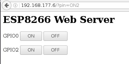
现在可以通过访问主机的页面http://192.168.177.6来设置LED了.
Arduino版LED
Arduino默认是不支持ESP的,需要安装插件来支持.
File -> Preferences -> Settings中, 如下图所示, 填json定义网址
http://arduino.esp8266.com/stable/package_esp8266com_index.json
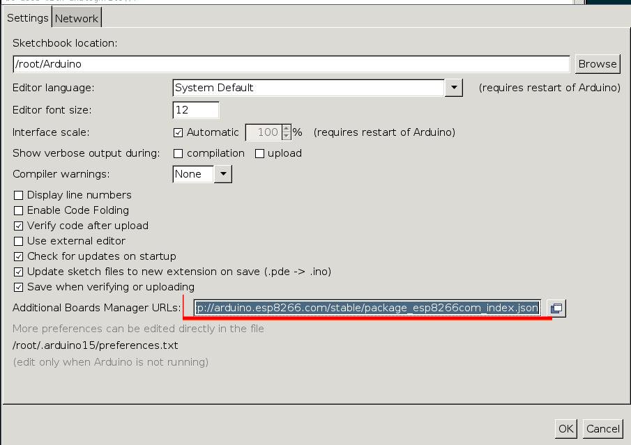
而后打开Tools -> Boards -> Board Manager, 自动刷新后, 安装ESP8266相关的库:
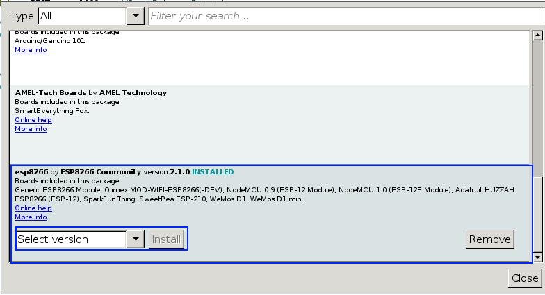
安装完毕后就可以使用ESP对应的Board了.
这里的代码实现了LED的闪烁, 源代码如下:
/*LED_Breathing.ino Arduining.com  20 AUG 2015
Using NodeMCU Development Kit V1.0
Going beyond Blink sketch to see the blue LED breathing.
A PWM modulation is made in software because GPIO16 can't
be used with analogWrite().
*/

#define LED     D0        // Led in NodeMCU at pin GPIO16 (D0).

#define BRIGHT    350     //max led intensity (1-500)
#define INHALE    1250    //Inhalation time in milliseconds.
#define PULSE     INHALE*1000/BRIGHT
#define REST      1000    //Rest Between Inhalations.

//----- Setup function. ------------------------
void setup() {
  pinMode(LED, OUTPUT);   // LED pin as output.
}

//----- Loop routine. --------------------------
void loop() {
  //ramp increasing intensity, Inhalation:
  for (int i=1;i<BRIGHT;i++){
    digitalWrite(LED, LOW);          // turn the LED on.
    delayMicroseconds(i*10);         // wait
    digitalWrite(LED, HIGH);         // turn the LED off.
    delayMicroseconds(PULSE-i*10);   // wait
    delay(0);                        //to prevent watchdog firing.
  }
  //ramp decreasing intensity, Exhalation (half time):
  for (int i=BRIGHT-1;i>0;i--){
    digitalWrite(LED, LOW);          // turn the LED on.
    delayMicroseconds(i*10);          // wait
    digitalWrite(LED, HIGH);         // turn the LED off.
    delayMicroseconds(PULSE-i*10);  // wait
    i--;
    delay(0);                        //to prevent watchdog firing.
  }
  delay(REST);                       //take a rest...
}
直接在Arduino IDE中编译验证即可.
