EBC Exercises on BBB -i2c and BBB
Nov 16, 2014
Technology
Connection
HMC5883L magnetometer runs in 400KHZ I2C bus, it’s for measuring the magnetic field vector in 3 dimensions.
We use its 4 ports: VCC,GND,SDA, SCL. SDA is for Data, while SCL is for Clock.
Use P9 for connecting the HMC5883L.
P9_02(GND) <----> GND
P9_04(VCC) <----> VCC
P9_19(I2C2_SCL) <----> SCL	 I2C bus 2(pin 19 on header p9 to SCL)
P9_20(I2C2_SDA) <----> SDA
I2C Detect
First you should install i2cdetect, then list the avaiable i2c bus via following command:
root@arm:~# i2cdetect -l
i2c-0   i2c             OMAP I2C adapter                        I2C adapter
i2c-1   i2c             OMAP I2C adapter                        I2C adapter
We choose i2c bus2, thus the command for detecting the connected device should be:
root@arm:~# i2cdetect -y -r 1
     0  1  2  3  4  5  6  7  8  9  a  b  c  d  e  f
00:          -- -- -- -- -- -- -- -- -- -- -- -- --
10: -- -- -- -- -- -- -- -- -- -- -- -- -- -- 1e --
20: -- -- -- -- -- -- -- -- -- -- -- -- -- -- -- --
30: -- -- -- -- -- -- -- -- -- -- -- -- -- -- -- --
40: -- -- -- -- -- -- -- -- -- -- -- -- -- -- -- --
50: -- -- -- -- UU UU UU UU -- -- -- -- -- -- -- --
60: -- -- -- -- -- -- -- -- -- -- -- -- -- -- -- --
70: -- -- -- -- -- -- -- --
The address should be 0x1e.
Communicate with HMC5883L
The registers are listed as following, notice eavh value for each axis are 16-bits, thus we have to read them seperately and combine them:
Address	Name	Access
00	Configuration Register A	Read/Write
01	Configuration Register B	Read/Write
02	Mode Register	Read/Write
03	Data Output X MSB Register	Read
04	Data Output X LSB Register	Read
05	Data Output Z MSB Register	Read
06	Data Output Z LSB Register	Read
07	Data Output Y MSB Register	Read
08	Data Output Y LSB Register	Read
09	Status Register	Read
10	Identification register A	Read
11	Identification register B	Read
12	Identification register C	Read
Thus we could read out the X MSB Restier and X LSB Register via:
root@arm:~# i2cget -y 1 0x1e 3
0xfe
root@arm:~# i2cget -y 1 0x1e 4
0x91
Different Mode
Notice Mode Register, this will set the mesurement mode.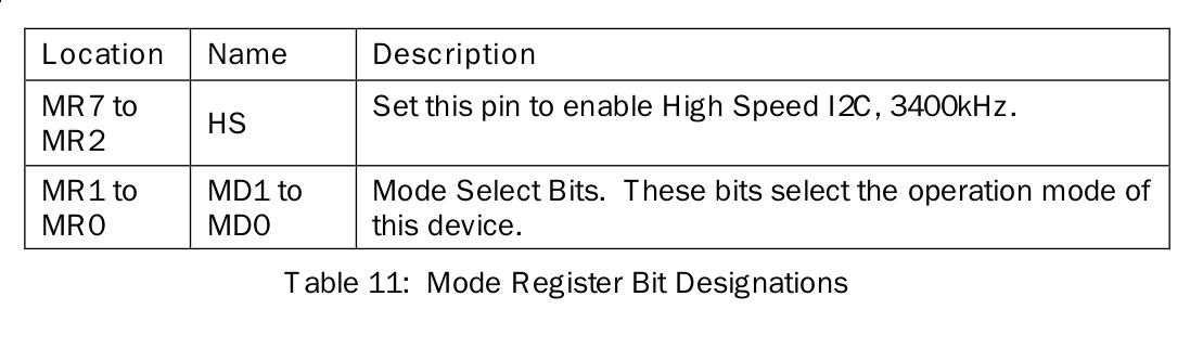
From the above table, we know for setting the lower 2 bits we could enable the operation mode of HMC5883L.
Now we set to single measurement mode, for one-time measure.
# i2cset -y 1 0x1e 2 1
2 means we set the register 2, and its number equals to 01(Single-Measurement Mode). After one-time measurement, it wil fall back to idle Mode.
After one-time measurement, get the register mode:
root@arm:~# i2cget -y 1 0x1e 2
0x03
Get the value of x-axis:
root@arm:~# i2cget -y 1 0x1e 3
0xfe
root@arm:~# i2cget -y 1 0x1e 4
0x77
C Code
Running Result:
root@arm:~/code/i2c# ./myi2cget 1 30 2
0x03 (3)
root@arm:~/code/i2c# ./myi2cget 1 30 34
0x00 (0)
root@arm:~/code/i2c# ./myi2cget 1 30 4
0x77 (119)
Critical Code:
Open the i2c-xxx:
        sprintf(filename, "/dev/i2c-%d", i2cbus);
        file = open(filename, O_RDWR);
ioctl for setting the address:
if (ioctl(file, I2C_SLAVE, address) < 0) {
Now read the byte from:
res = i2c_smbus_read_byte_data(file, daddress);
Comparing the official i2cget, myi2cget could print out the human-readable format of data.
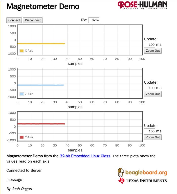
Web Displaying
Git clone the following project form github.com:
# git clone https://github.com/duganje/ECE497_duganje.git
# cd  ECE497_duganje/
# ls
MiniProject01  MiniProject02  MiniProject03  MiniProject04  README.md
Upload the project MiniProject04 to the BBB board.
Notice change the code in buttonBox.js from i2cset -y 3 to i2cset -y 1 and i2cget -y 3toi2cget -y 1`
After modification, run buttonBox.js via:
$ node buttonBox.js
Now visit the http://xx.xx.xx.xxx:8081/buttonBox.html you could see the data displayed as following: